PROSWING(M)
Operating instruction
36
Wiring and use for double Proswing
Double Proswing is an automatism for double door.
It is possible to realize a double door in two ways:
1. with two Proswing installed on each door and then connected together ;
2. with two Proswing installed on each door and connected together by a extension kit (OPTIONAL).
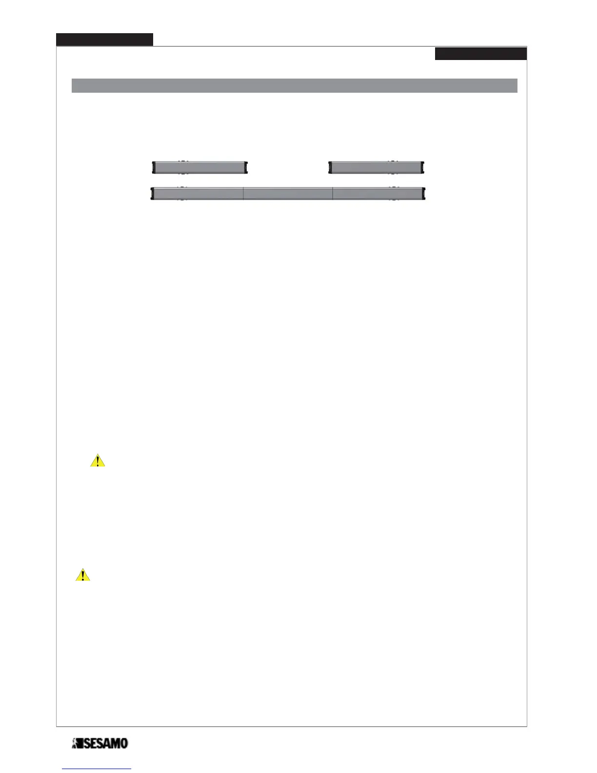
SOLUTION 1
SOLUTION 2
The two Proswing, through a wiring on the selector terminal board, can exchange information in order to rightly drive the
two doors. It is needed to set one control door as a Master and one as a Slave. The Slave acts only the Master command.
For solution 1 proceed as follows:
1- remove all components on both automatisms (in order : covers, end cap, control boards, motor gears, transformers);
2- fix the aluminum base of each single automatism on the relevant door following instructions described at paragraph
“aluminum base holes positioning” – depending on the type of arm used;
3- connect together selectors terminal board in order to allow communication between the two cards (Fig. 36)
4- assemble again all the components taking care of disconnecting the selector switch of slave door (see Fig. 45)
For solution 2 proceed as follows:
1- remove all components on both automatisms (in order : covers, end cap, control boards, motor gears, transformers);
2- put the two aluminum base and the central joining base on a plane surface (Fig. 34);
3- insert each base under the tongue of the two joining parts as showed (Fig. 35);
ATTENTION: Maintain the orientation of the aluminum bases as shown in Fig 46, so that the black end caps are
positioned at the ends.
4- tighten screws (Fig. 45 part A)in order to obtain one single piece;
5- fix the piece to the structure or wall following the instruction and positioning dimensions described at the paragraph
“aluminum base holes positioning” and paragraph of the arm depending on the type used;
6- connect together selectors terminal board in order to allow communication between the two cards (Fig. 36);
7- assemble again all the components except end caps. As end caps use th two supplied with the extension positioning
the one with logic and power switches on the master door and the one with only power switch on slave door.
ATTENTION: for both cases define, before making any connections, the door and the door Slave Master.
Conventionally:
MASTER DOOR: is the first in opening and the last in closing (in case displacement)
SLAVE DOOR: is the second in opening and first in closing (in case displacement).