G
F
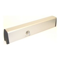
Fig. 41
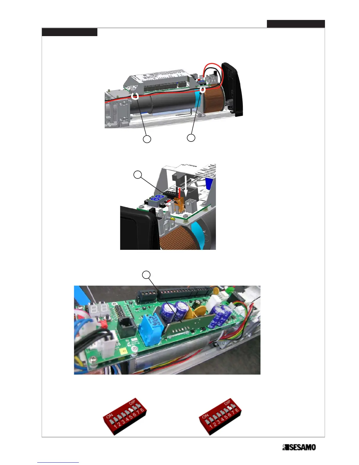
Fig. 42
H
I
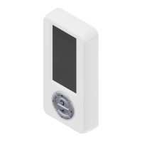
Fig. 43
4- Pass cables through springs (E) , then under the control board until the part of control board where is located the
transformer Fig. 41. Fix cables as shown in Fig . 41 (F) and (G).
5- Connect the batteries cables terminal board to control board Fig. 42 (H)
6- Insert control board for batteries (I) on main control board Fig 43
7- Set dip switch 7 =ON and dip switch 6 (=OFF if it is required continuous use after power failure or =ON if it is requi-
red stop open after power failure)- Fig. 44.
Fig. 44
41
PROSWING(M)
Operating instruction