Setra FLEX Operating Instructions
20
Phone: (800) 257-3872 | Fax: (978) 264-0292 | www.setra.com
(CONTINUED FROM PREVIOUS PAGE)
• Room 3 Pressure – the Output is driving a signal from
Room 3 Pressure badge
• Room 3 Temperature – the Output is driving a signal
from Room 3 Temperature badge
• Room 3 Humidity – the Output is driving a signal from
Room 3 Humidity badge
• Room 3 ACH – the Output is driving a signal from Room
3 Air Changes per Hour (ACH) badge
• Room 3 User Dened – the Output is driving a signal
fromRoom3’srstUserDenedbadge
• Room 3 User Dened – the Output is driving a signal
fromRoom1’ssecondUserDenedbadge
• Control Loop 1 – the Output signal is being controlled
by Control Loop 1’s PI algorithm
• Control Loop 2 – the Output signal is being controlled
by Control Loop 2’s PI algorithm
• Control Loop 3 – the Output signal is being controlled
by Control Loop 3’s PI algorithm
• Control Loop 4 – the Output signal is being controlled
by Control Loop 4’s PI algorithm
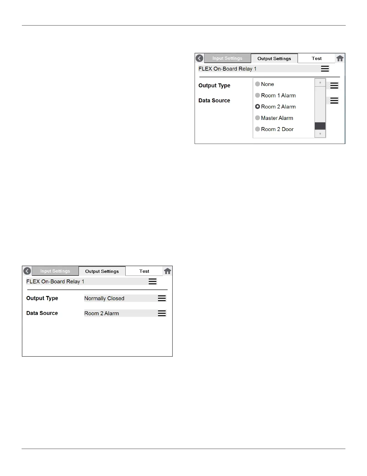
Relay Settings
There is one relay contact available on the back of the
FLEX unit. When “On-Board Relay” is selected, the Output
Type available is either “Normally Closed” or “Normally
Open.”
Choose the Data Source that will drive the relay. Examples
appear below:
Data Source can be selected as one of the following:
• None – the Relay has no Data Source driving it
• Room 1 Alarm – the Relay changes state when an alarm
occurs in Room 1
• Room 2 Alarm – the Relay changes state when an alarm
occurs in Room 2
• Room 3 Alarm – the Relay changes state when an alarm
occurs in Room 3
• Master Alarm – the Relay changes state when any
alarm occurs in any room and on any parameter
• Room 1 Door – the Relay changes state when the Door
contact changes state in Room 1
• Room 2 Door – the Relay changes state when the Door
contact changes state in Room 2
• Room 3 Door – the Relay changes state when the Door
contact changes state in Room 3