Signal wiring
Assemble your wiring harness using wire of the sizes recommended below and the Sevcon loose
connector kit (P/N 661/27091). The use of twisted pair and in some cases twisted-screened
cables is recommended for the speed sensor and CANbus wiring.
To make a connection, gently push the connector housing onto the appropriate mating half on
the Gen4. Never force a connector. Connectors are keyed to prevent incorrect insertion.
Twisted, shielded wire is recommended. Keep signals away from power cables to avoid
interference. See also ‘EMC guidelines’ on page 3-6.
Signal wire sizes
Use wire between 0.5 mm² (20 AWG) and 1.5 mm² (16 AWG) for all signal wiring. Single twisted
pair cable is readily available in 0.5 mm² (20 AWG).
CANbus termination
See also ‘EMC guidelines’ on page 3-6.
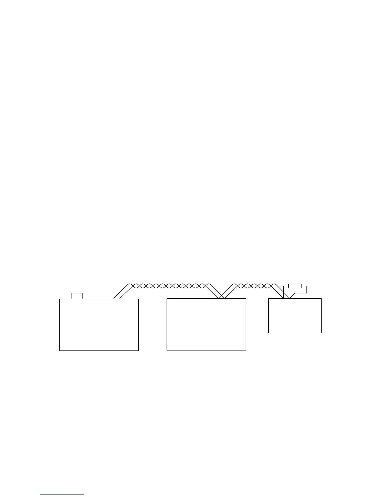
If your system has more than one CAN node, connect the nodes in a ‘daisy chain’ arrangement
(Figure 8) and terminate the connections of the two end nodes with a 120 resistor. If the end
node is a Gen4, link pins 2 and 24 on the customer connector, a 120 resistor is built into the
controller. If you have a single node system the termination resistor should be connected so that
the bus operates correctly when configuration tools are used.