Encoder PPR is set at 6090
h
. Additional encoder configuration (pull-up, supply, etc) is set at
4630
h
.
Encoder PPR (6090
h
) must be configured correctly to ensure reliable control of the motor.
Failure to do so could cause the controller to output incorrect torque.
Motor commutation sensor
UVW Commutation Sensors
Commutation sensors are designed to measure the position of the rotor shaft within the motor,
rather than its rotational speed. Rotor position information is used for control of permanent
magnet motors, as it allows the controller to energise the motor phases appropriately based on
the measured position of the magnets on the rotor.
The Gen4 controller provides inputs for both digital UVW style position sensors and analogue
sin-cos sensors. Either of these can be used for control of permanent magnet motors.
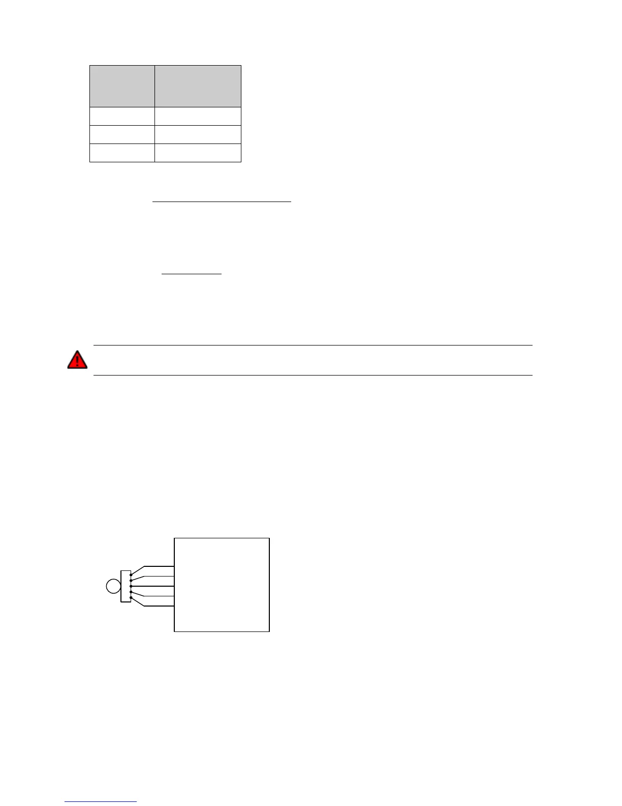
Figure 17 - Sample wiring for a UVW commutation sensor
3 digital inputs are provided for UVW encoders. The encoder should provide one pulse on each
channel per electrical cycle of the motor, and each pulse should be 120° out of phase with the
others and have a 50% duty cycle: