Figure 18 - Example pulse train from a UVW commutation sensor
UVW encoder power supply can be configured with 5V or 10V supply voltage. For 10V supply
the low to high transition threshold is 5.3V and for 5V supply it is 2.7V
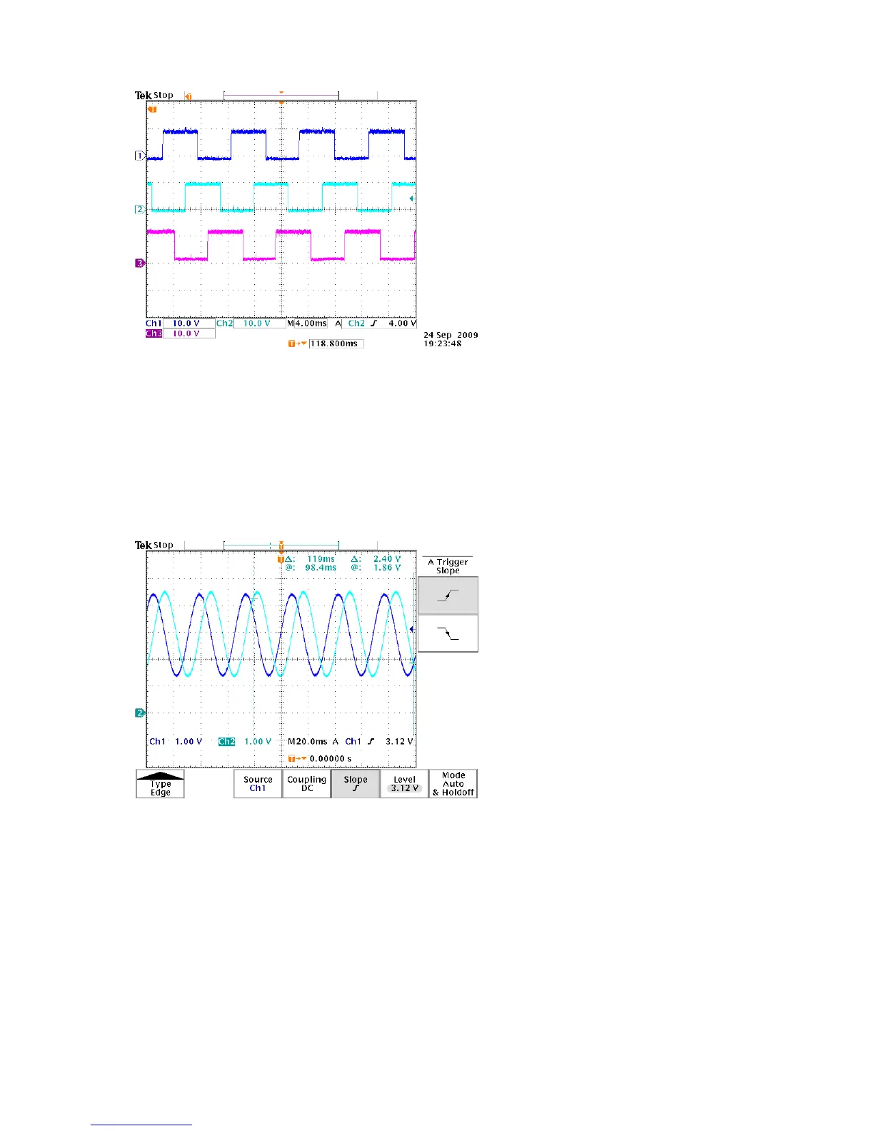
Sin-Cos Commutation Sensor
Analogue sin-cos encoders should provide one sine wave and one cosine wave per mechanical
rotation of the motor. Peak and trough signal voltages must have a minimum of 1V difference.
Figure 19 - Example of signals from a sin-cos position sensor