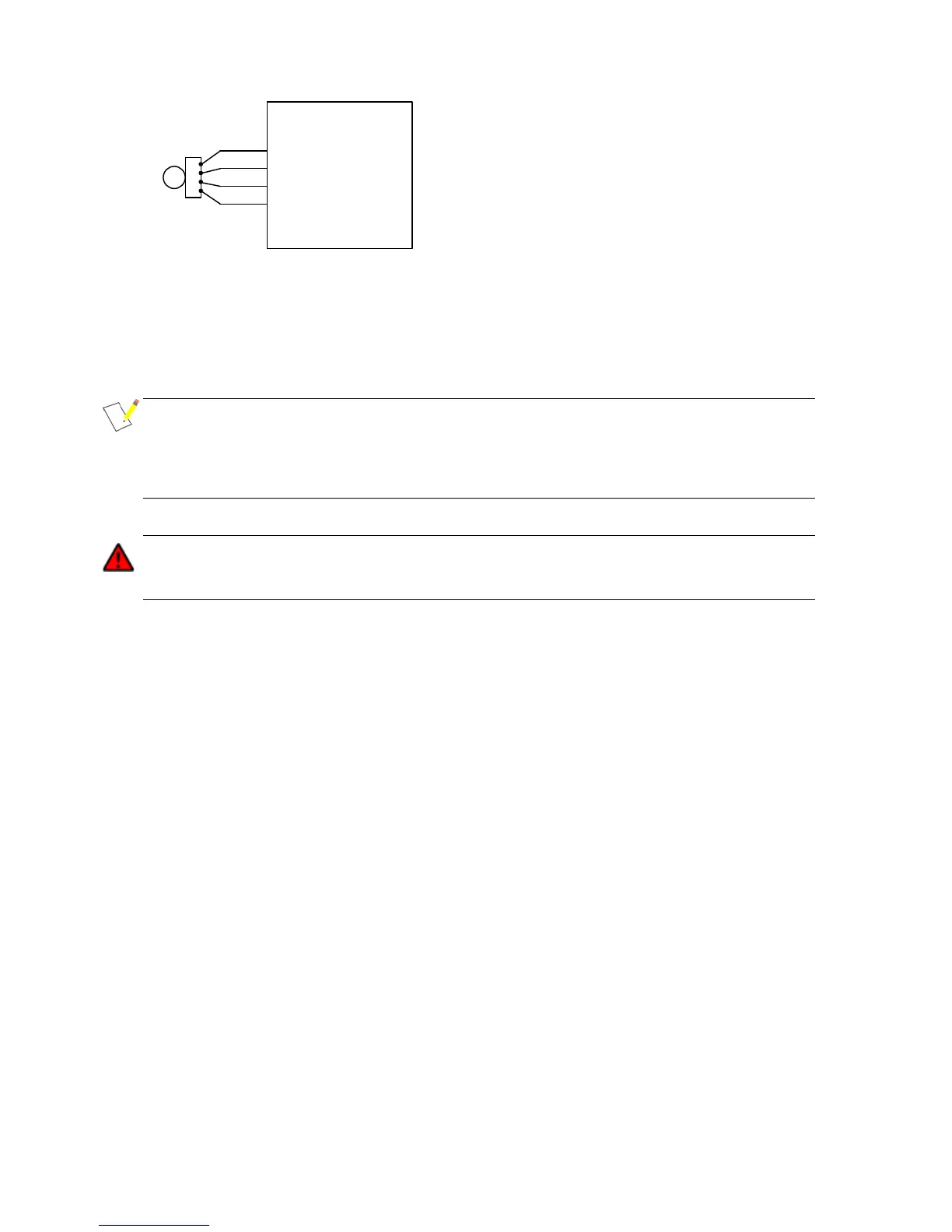
Figure 20 - Sample wiring for a sin-cos commutation sensor
Sin-cos encoders are typically powered by a 5V supply. Therefore it is important to ensure that
the controller is configured to supply 5V on pin 26. This should be done by setting the encoder
configuration object dictionary entry at 4630
h
.
NOTE: The standard Gen4 build does not provide inputs for the sin and cos signals. Therefore, if
operation with a sin-cos analogue encoder is required then this must be specified as a hardware
build option. Controllers built for use with sin-cos encoders have the functions of pins 31 and 35
reassigned from digital and analogue inputs to sin and cos signal inputs respectively. Please
contact your local dealer for more information on the sin-cos encoder build option.
Encoder offset (4630
h
,4+16), Sin/Cos Waves/Mechanical Revolution (4630
h
,14) and
Sin/Cos Latency (4630
h
,15) must be configured correctly to ensure reliable control of the
motor. Failure to do so could cause the controller to output incorrect torque.