Signal connections
CAUTION: Do not use contactors which have built in ‘economiser’ circuits, the internal circuits
are not compatible with the controller and may cause malfunction or damage. The same power
reduction can be achieved with a standard coil by using the configurable pull-in and hold voltage
settings.
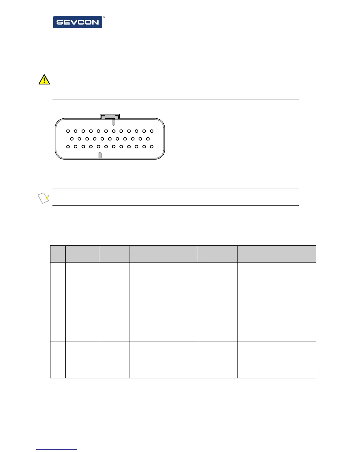
Signal connections are made to Gen4 via a 35 way AMPSeal connector.
Figure 9 Customer Connector
Pins are protected against short-circuits to the battery positive or negative terminals.
NOTE: Please see Tyco Application Specification 114-16016 and Instruction sheet 408-3229
before assembling the AMPseal connector.
Inserting contacts into connector housing pierces the sealing diaphragm to make the seal to the
wire. To maintain IP rating, unused positions must be sealed with appropriate hardware
(available from Tyco) if a contact is inserted and then subsequently removed. It is recommended
that Tyco strain relief 776463-1 is used (especially for applications where the connector is less
than fully populated) to reduce change of ingress through connector body.
This input supplies power
from the battery for all the
logic circuits.
The unit cannot operate
without “Key switch in”
supply.
Pins 1 and 6 (and 10 on
Size 4 & 6 models) are
connected together
internally and can be used
individually or in parallel.
To terminate a Gen4 CAN node link pin
2 to pin 24. This connects a 120Ω
termination resistor, mounted inside the
controller, across the CANbus.
Make the connection only if
the Gen4 is physically at the
end of the CANbus network
(see ‘CANbus termination’
on page 3-13.