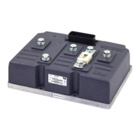
Twin motor systems
A twin motor system may be powered by two Gen4 controllers operating in master–slave
configuration. In this case the necessary commands are transmitted by the master node to the
slave node via the CANbus.
Motors may be operated independently in a combined traction-pump application or operated in
tandem where each motor drives a separate wheel. In this latter case the controller (where there
are two controllers, the controller configured as master):
Assists in the steering of a vehicle by adjusting the torque of each motor dependent on the
steering angle.
Reverses the direction of the inner wheel in order to provide a smaller turning circle. The
speed of the outer wheel is also limited during a turn.
An example of possible wiring for Gen4 traction controllers operating in master-slave
configuration is shown in Figure 15.
Auxiliary components
Main contactor
Select the appropriate contactor line contactor from Table 4. A line contactor used at its rated coil
voltage must be rated ‘continuous’. Contactor coil voltage chopping allows the use of coils rated
‘intermittent’, provided the manufacturer’s conditions are met.
Table 4 Main contactor rating
The controller can drive any contactor with coil voltages from 12 V to Vb. It is worth considering
the use of 24 V contactors with the contactor drive output set to voltage-control mode. This
allows you to use one type of contactor for any battery voltage (24 V to 80 V). Pull-in voltage,
pull-in time and hold-in voltage values are all configurable.
Contactor coils must not be wired to the supply side of the key switch. Use the Output 1 Supply /
Output 2 Supply / Output 3 Supply pins provided (see Table 2).
35 Way AMPSeal Connector Kit
Kit consists of Gen4 mating 35 way AMPSeal connector and pins, Sevcon p/n 661/27091
Emergency stop switch
Refer to the appropriate truck standards.

 Loading...