EasyManuals Logo

SEW-Eurodrive MOVIDRIVE MDA Series User Manual

SEW-Eurodrive MOVIDRIVE MDA Series
288 pages
To Next Page IconTo Next Page
To Previous Page IconTo Previous Page
Page #145 background imageLoading...
Page #145 background image
4
Installation
Wiring diagrams
Operating Instructions – MOVIDRIVE
®
modular
145
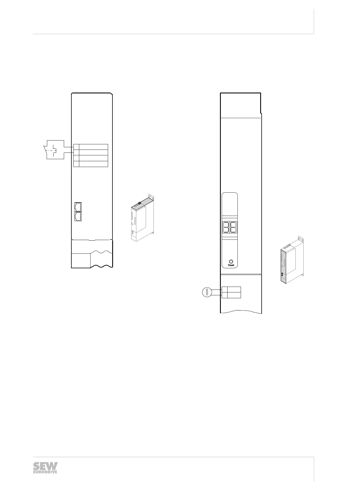
4.13.4 Electronics connection MDP90A.. power supply module
Wiring the control electronics
For the terminal assignment and connections, refer to chapter "Terminal assign-
ment"(→2123).
X7
X30 OUT
X30 IN
X5
+24 V
GND
DC 24 V
+
-
2
1
3
4
+T emp_R
-T emp_R
[1]
reserved
reserved
36028811332832523
[1] Signal contact of the thermal monitoring of the braking resistor
X5 Connection +24V supply voltage
X7 Control DC link discharge module, temperature monitoring braking resistor
X30 System bus
24748536/EN – 11/2017

Table of Contents

Questions and Answers:

Question and Answer IconNeed help?

Do you have a question about the SEW-Eurodrive MOVIDRIVE MDA Series and is the answer not in the manual?

SEW-Eurodrive MOVIDRIVE MDA Series Specifications

General IconGeneral
BrandSEW-Eurodrive
ModelMOVIDRIVE MDA Series
CategoryControl Unit
LanguageEnglish

Related product manuals