3
Unit structure, axis system structure
Unit structure of the MDA and MDD axis modules
Operating Instructions – MOVIDRIVE
®
modular
41
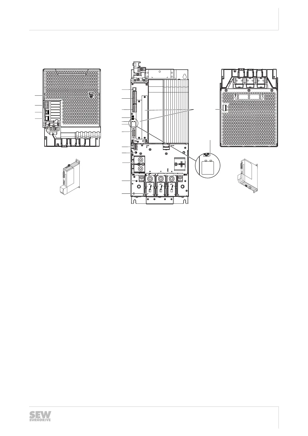
3.5.5 MDA90A-1400, 1800 (size 6) – Single-axis module
X30 OUTX30 IN
A CB
RUN ERR
X15
X21 X20 X31
S1
S2
[11]
[5]
[6]
[7]
[8]
[10]
[9]
RUN ERR
[9]
[3]
[4]
[1]
X6
1
2
3
4
5
[2]
[12]
[13]
[14]
[15]
[16]
X10
[18]
[17]
20106024075
A: View from top B: View from front C: View from bottom
[1] Terminal screw for TN/TT systems [5] X31: SEW‑EURODRIVE Service inter-
face
[18] X10: Brake control and temper-
ature monitoring motor
[2] X6: Connection for Safe Torque Off
(STO)
[6] X20: Digital inputs
[3] X30 OUT: System bus [7] X21: Digital outputs
[4] X30 IN: System bus [8] EtherCAT
®
ID switch
[9] Status LEDs EtherCAT
®
/SBus
PLUS
"RUN",
"ERR"
[10] 7-segment display
[11] X15: Motor encoder connection
[12] X5: Connection +24V supply voltage
[13] PE connection
[14] X4: DC link bus connection
[15] PE connection housing
[16] X2: Motor connection
[17] Card slots
24748536/EN – 11/2017

 Loading...