6
Operation
7-segment display
Operating Instructions – MOVIDRIVE
®
modular
160
6.2 7-segment display
6.2.1 Operating displays
• The two 7-segment displays indicate the operating state of the power supply
modules and axis modules.
• The displays for the axis modules and the power supply modules are therefore
described separately.
6.2.2 Fault display
The application inverter detects any faults that occur and displays them as fault code.
Each fault is clearly defined by its fault code and corresponding attributes, as shown
below:
• Fault response
• Final state after executing the fault response
• Type of reset response.
The fault codes are indicated as flashing numeric values in the axis and power supply
module.
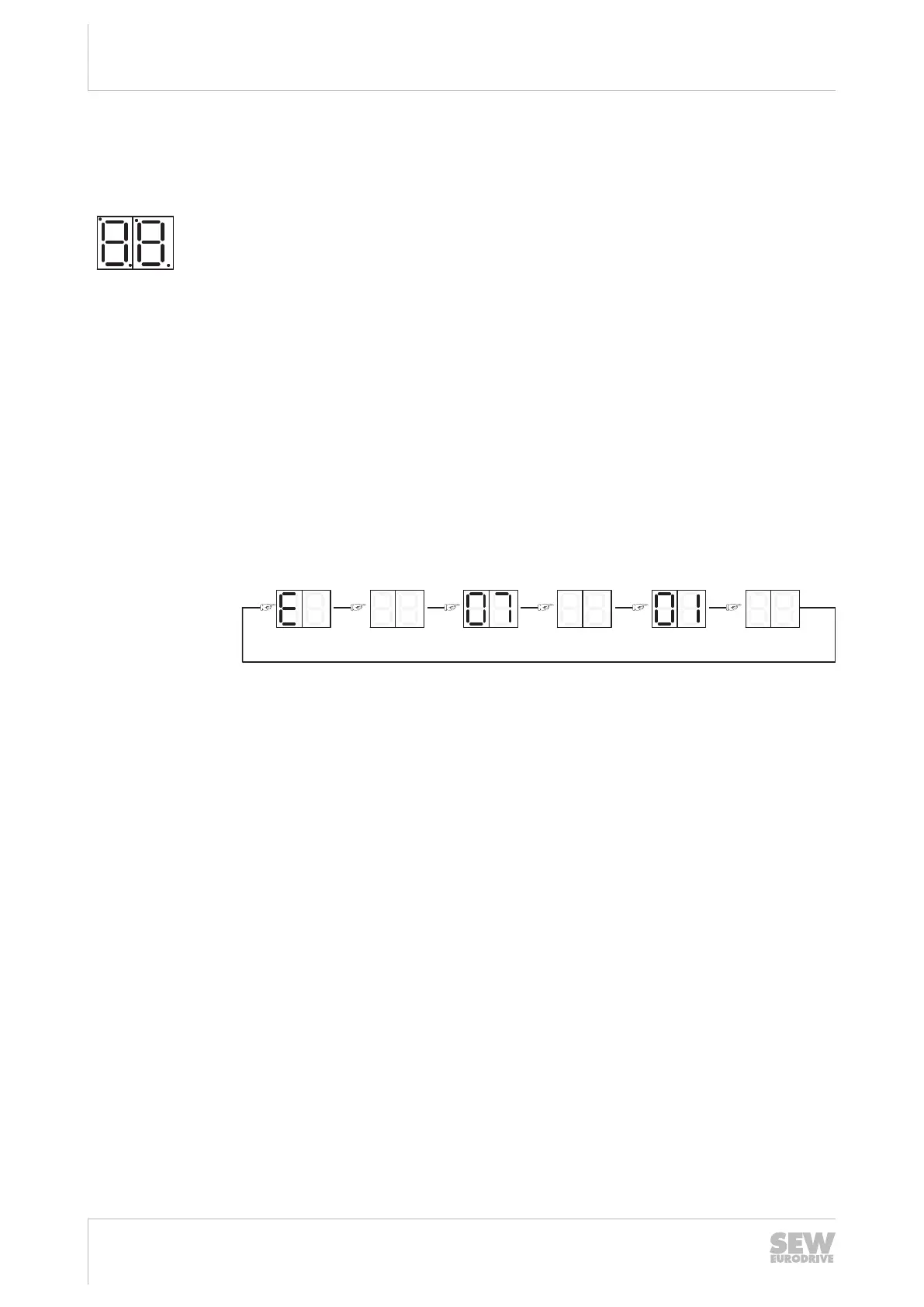
The fault code is displayed in the following display sequence:
500 ms 124 ms 1000 ms 124 ms
12082058123
In the example, a 2-digit fault code with subfault is shown at the axis module, fault
07.01 in this example.
Fault display at the double-axis module
The double-axis module has one two-digit 7-segment display for each of the two integ-
rated axes. They are located horizontally next to each other. The left display applies to
axis 1, the right one to axis 2.
24748536/EN – 11/2017

 Loading...