4
Installation
Wiring diagrams
Operating Instructions – MOVIDRIVE
®
modular
146
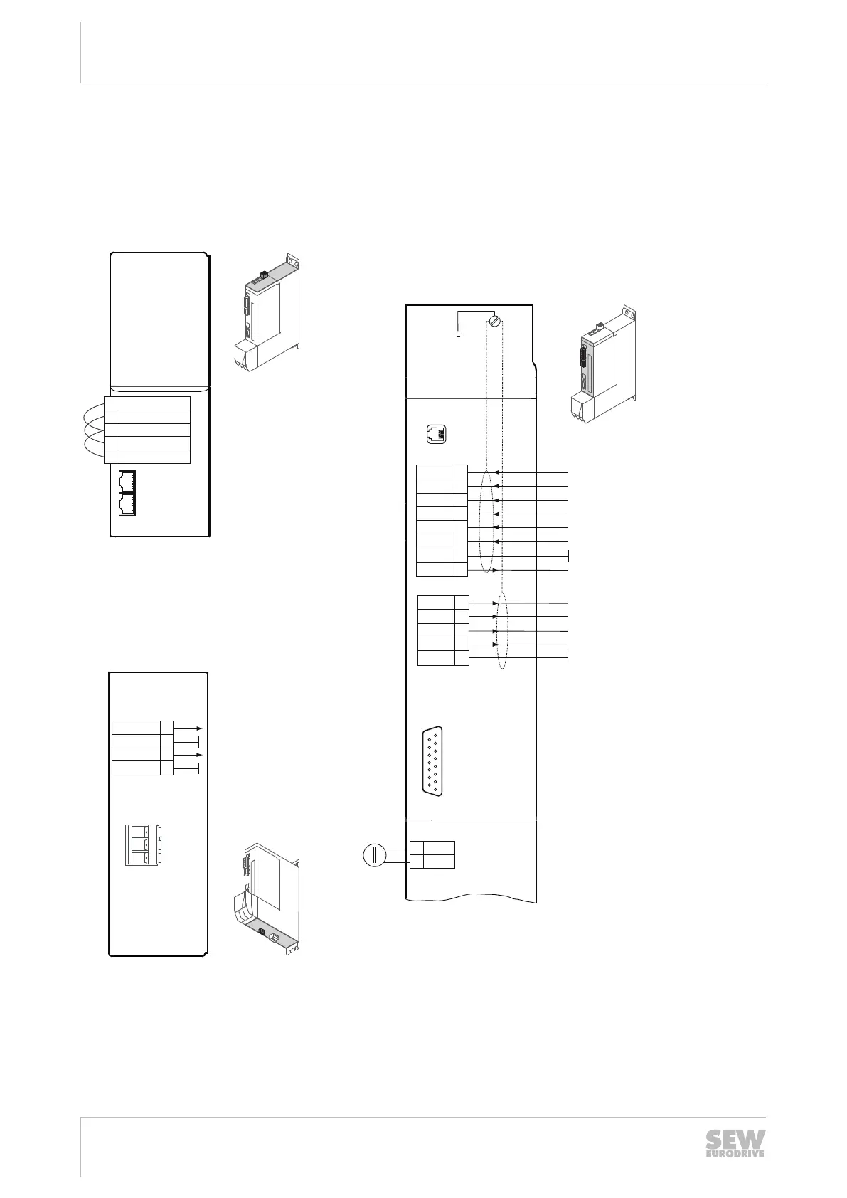
4.13.5 Electronics connection MDA90A.. single-axis module
Wiring the control electronics
For the terminal assignment and connections, refer to chapter "Terminal assign-
ment"(→2123).
2
X20
1
3
4
5
6
8
7
DI00
DI01
DI02
DI03
DI04
DI05
GND
24V
2
X21
1
3
4
5
DO00
DO01
DO02
DO03
GND
X31
X15
15
14
13
12
11
10
9
4
5
6
7
1
2
3
8
PE
Fixed assigment “Output stage enable”
Digital input
Reference potential for digital inputs
DC 24 V auxiliary voltage output
Reference potential for digital outputs
DB00
GND
TF1
GND
X10
X30 OUT
X30 IN
X6
Brake control
Reference potential
Reference potential
Temperature evaluation motor
Digital input
Digital input
Digital input
Digital input
Digital ouput
Digital ouput
Digital ouput
Digital ouput
2
1
3
4
5
F_STO_P1
F_STO_M
F_STO_P2
GND
24VSTO_OUT
X5
+24 V
GND
DC 24 V
+
-
9007216007198987
X5 Connection +24V supply voltage X20 Digital inputs
X6 Connection for safe disconnection (STO). Cable jumpers are installed at factory. X21 Digital outputs
X10 Brake control and temperature monitoring motor X30 System bus
X15 Motor encoder connection X31 SEW‑EURODRIVE Service inter-
face
24748536/EN – 11/2017

 Loading...