AL-1551CS UNPACKING AND INSTALLATION 5 - 8
4. When the "Select Program Folder" window appears, click the
"Next" button.
The setup program will start to copy the files.
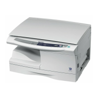
If the dialog box asking "If you have TIFF files saved using
Photo-Shop or Imaging for Windows you should hit Skip"
appears. Answer the question to continue the Sharpdesk instal-
lation.
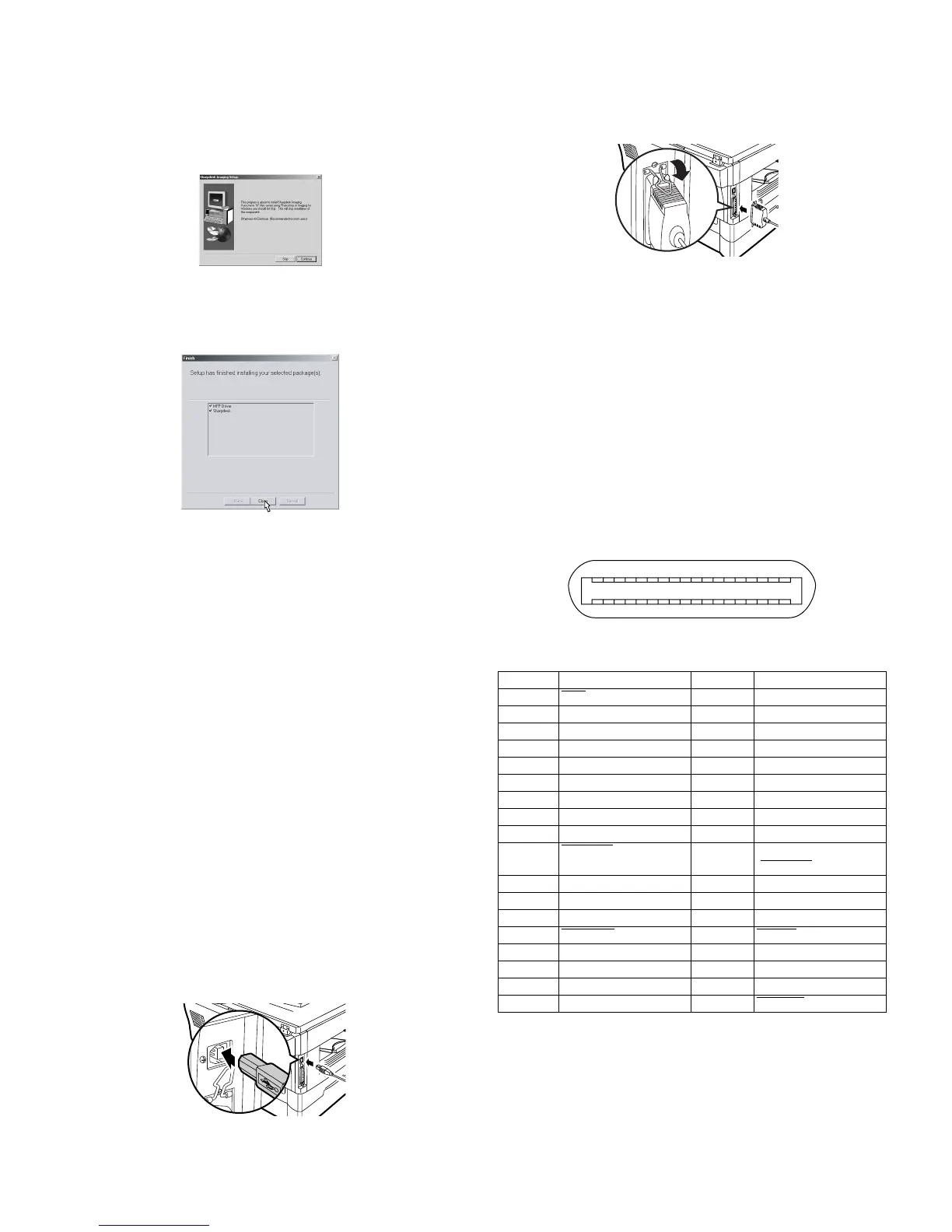
5. Click the "Finish" button when the message to inform you of the
completion of the installation appears.
9) Click the "Close" button when the message to inform you of the
completion of the installation appears.
• After the installation, a message to restart your computer may be
displayed. In this case, click the "Yes" button to restart your com-
puter.
10) Connect the parallel interface cable.
You have completed the installation of all the software.
• For parallel interface connection ensure that your computer and
MFP are turned off before connecting the cable (see page 5-8).
10. Connecting the interface cable
This unit includes both USB and parallel interface connectors.
Interface cables for connecting the unit to your computer are not
included with this unit.
Caution:
• If you intend to use the unit as a scanner, it must be connected to
your computer with a USB interface cable. The scanner function can-
not be used if the unit is connected with a parallel cable.
• USB is available with a PC/AT compatible computer that was origi-
nally equipped with USB and had Windows 98, Windows Me, Win-
dows 2000 Professional, Windows XP Professional or Windows XP
Home Edition preinstalled.
• Do not connect the interface cable before installing the MFP driver.
The interface cable should be connected during installa-tion of the
MFP driver.
Connecting the USB interface cable
1) Obtain a shielded USB interface cable.
2) Insert the cable into the USB interface connector located on the
rear of the unit.
3) Insert the other end of the cable into the interface connector of your
computer, or the USB hub connected to your computer.
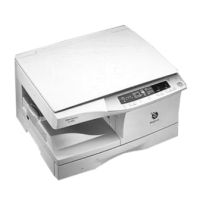
Connecting the parallel interface cable
1) Obtain an IEEE1284 shielded parallel interface cable.
2) Ensure that your computer and unit are turned off.
3) Insert the cable into the parallel interface connector located on the
rear of the unit, and fasten with clasps.
4) Insert the other end of the cable into the interface connector of your
computer.
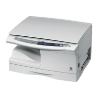
11. Parallel interface
This printer uses a bi-directional parallel interface. Use the supplied
interface cable.
Connector
36-pin ACON RBE42-36K1153 female connector or equivalent con-
nector
Cable
Shielded type bi-directional parallel interface For best results, use a
printer interface cable which is IEEE1284 compliant.
Pin configuration
The pin numbers and signal names are listed in the following table.
Pin No. Signal name Pin No. Signal name
1STB
19 GND (STB RET)
2 DATA1 20 GND (DATA1 RET)
3 DATA2 21 GND (DATA2 RET)
4 DATA3 22 GND (DATA3 RET)
5 DATA4 23 GND (DATA4 RET)
6 DATA5 24 GND (DATA5 RET)
7 DATA6 25 GND (DATA6 RET)
8 DATA7 26 GND (DATA7 RET)
9 DATA8 27 GND (DATA8 RET)
10 ACKNLG
28 GND
(ACKNLG
RET)
11 BUSY 29 GND (BUSY RET)
12 PE (Paper End) 30 GND (PE RET)
13 SLTC 31 INPRM
14 AUTO LF
32 FAULT
15 (NC) 33 (NC)
16 GND (0 V) 34 (NC)
17 FG 35 +5 V
18 +5 V 36 SLTC IN
1
18
36 19