: Feb. 9 2004
1
AR-M550/M620/M700 SETTING AND ADJUSTMENTS 7 - 2
Note: Adjusting the output voltage requires the ability to measure
internal impedance of 1000 MW.
This adjustment is needed in the following situations:
• The high voltage power PWB (MC/DV/TC) has been replaced.
• U2 trouble has occurred.
• The PCU PWB has been replaced.
• The EEPROM of the PCU PWB has been replaced.
(Main charger grid voltage adjustment)
1) Remove the rear cover of the machine.
ADJ11 Adjusting the image quality in scan mode ADJ 11A Adjust the scan mode image density for all modes at once 46-21
ADJ 11B Scan mode image density adjustment/individual setup
(standard mode)
46-21, 46-22,
46-23, 46-24,
46-25
ADJ 11C Scan mode image density adjustment/individual setup
(small-character mode)
ADJ 11D Scan mode image density adjustment/individual setup
(fine mode)
ADJ 11E Scan mode image density adjustment/individual setup
(super fine mode)
ADJ 11F Adjust the image gamma in scanner mode 46-27
ADJ12 Common image quality adjustments for all of
copy, scan, and fax modes
ADJ 12A
Correct the image density in original table mode/SPF
mode (Copy mode)
46-20
ADJ 12B Set up the auto mode operation for copy, scan, and fax 46-19
ADJ 12C Adjust the shading reference value (gain adjustment) 46-17
ADJ13 Adjusting the fusing paper guide position
ADJ 14 Adjusting the paper size detection ADJ 14A Adjust the paper width sensor for the manual paper feed
tray
40-2
ADJ 14B Adjust the paper width sensor for paper feed tray 3 40-12
ADJ 14C Adjust the paper width sensor for the SPF paper feed tray 53-6
ADJ 15 Adjusting the original size detection (in original
table mode)
ADJ 15A Adjust the detection point of the original size sensor (in
original table mode)
41-1
ADJ 15B Adjust the sensitivity of the original size sensor
41-2
ADJ16 Adjusting the touch panel coordinates 65-1
ADJ17 Adjusting the supply voltage
Job No Adjustment item list Simulation
1
1
1
1
ADJ 1 Adjusting high voltage values
ADJ 1A Adjust the main charger grid voltage
Item/operation mode
Simulation
High voltage power PWB (MC/DV/TC)
Setting range Default Connector Pin # Actual voltage
Copy Auto mode 8-2 AUTO 200 – 1000 580 CN2 3
–590±2v
Text mode CHARACTER 200 – 1000 580 CN2 3
–590±2v
Text/photo mode MIX 200 – 1000 580 CN2 3
–590±2v
Photo mode PHOTO 200 – 1000 580 CN2 3
–590±2v
Printer All modes PRINTER 200 – 1000 580 CN2 3
–590±2v
FAX All modes FAX 200 – 1000 580 CN2 3
–590±2v
1
1
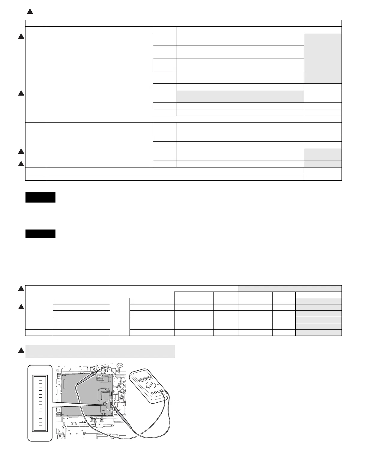
2) Apply a digital multi-meter to the connector CN2 pin (3) of the high
voltage PWB and the chassis GND.
1
CN2
3
 Loading...