MX-M753N MX-LCX3N 3 – 6
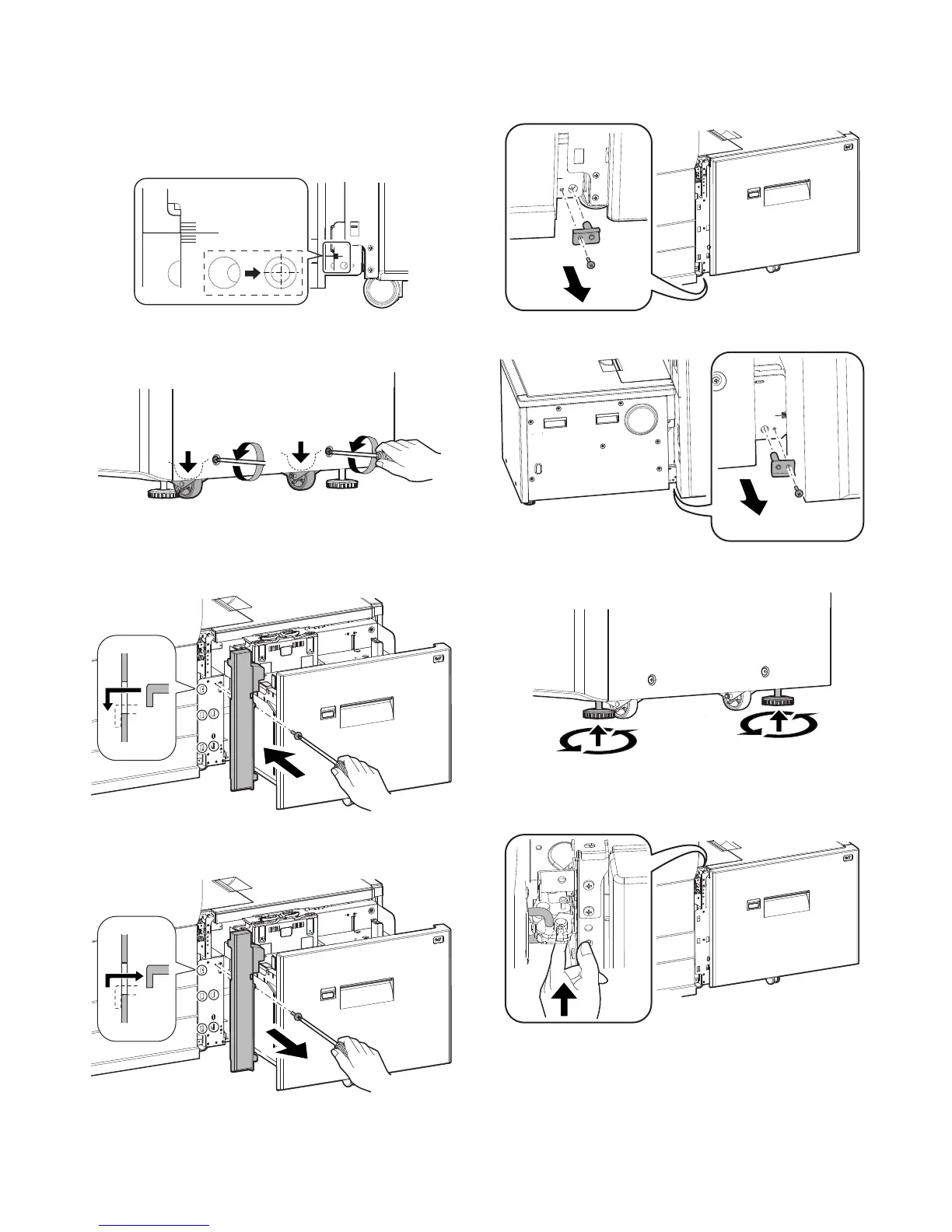
• When the upper side is not locked
Raise the adjuster on the lower side of the LCC right side until
the hole shown in the figure below comes at the center, and
check that it is locked.
* If lock is incomplete, when the power switch is turned on, the
message, “Check installation of tray 5” is displayed on the
operation panel.
3) Check that the right caster section is grounded.
Loosen two screws on the lower side of the LCC right side,
ground the caster on the floor, and tighten the screws.
4) Installation of the left front cabinet
Engage the pawls of the left front cabinet with the five square
holes in the left front side of the LCC, and press the left front
cabinet and fix with the fixing screw C (1 pc).
[How to separate the LCC from the machine]
1) Remove the left front cabinet of the LCC.
2) Remove the positioning plate installed to the front and the rear
sides of the left lower side of the LCC.
F side
R side
3) Raise the adjuster installed to the front and the rear sides of
the lower section of the LCC right side.
4) Push the resin cover beneath the lock section on the top of the
left side of the LCC and shift the LCC to the right. Release the
top lock.
 Loading...