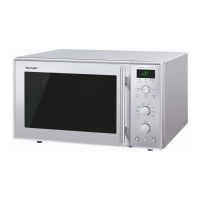
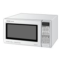
TURNTABLE
MOTOR
REMOVAL
1. Disconnect the oven from the power supply and remove
the outer case.
2. Discharge the high voltage capacitor.
3. Remove the screw holding the door open angle of the
base cabinet
(B)
to the door.
4. Remove the seven (7) screws. holding the base cabinet
(B) to the oven cavity and back cabinet.
1
5. Shift the base cabinet (B) to the left to release the tab
of the base cabinet
(B)
from the base cabinet (A).
6. Remove the base cabinet (B).
7. Disconnect the wire leads from the turntable motor.
8. Remove the four (4) screws holding the turntable mo-
tor mounting bracket to the oven cavity bottom.
9. Remove the turntable motor with the mounting brack-
et attached.
IO. Remove the four (4) screws holding the mounting
bracket to the motor.
The turntable motor is now free.
MAGNETRON
ASSEMBLY
REMOVAL
1. Disconnect the oven from the power supply and re-
move the outer case.
2. Discharge the high voltage capacitor.
3. Disconnect the wire leads from the magnetron assemb-
ly and the therm0 cut-out.
4. Release the tab which is provided on the cooling duct
(B) to hold the cooling duct (A), Figure 30.
5. Carefully remove the four (4) mounting nuts holding
the magnetron assembly to the waveguide while
supporting the magnetron assembly from below.
6. Lower the magnetron assembly until the tube is clear
of the waveguide.
7. Remove the two (2) screws and washers holding the
cooling duct (B) to the magnetron assembly.
8. Remove the cooling duct (B) from the unit.
9. Remove the
therm0
cut-out by loosening the mounting
screws.
CAUTION: WHEN REPLACING THE MAGNETRON,
BE SURE THE R.F. GASKET IS IN PLACE
AND THE MAGNETRON MOUNTING
NUTS ARE TIGHTENED SECURELY.
COOLING
FAN
MOTOR
REMOVAL
1. Disconnect the oven from the power supply and remove
the outer case.
2. Discharge the high voltage capacitor.
3. Disconnect the wire leads from the cooling fan motor.
4. Release the wire leads from surround the cooling duct
(A).
5. Remove the four (4) screws holding the chassis support
to the back cabinet, cooling duct (A), convection motor
mounting plate and control panel back plate.
6. Release the tab which is provided on the cooling duct
(B) to hold th
e cooling duct (A).
7. Remove the duct (A) with the cooling fan motor
attached from the unit.
The cooling fan motor assembly is now free.
8. Remove the fan blade from the cooling fan motor shaft
by pulling the fan retainer clip.
9. Remove the two (2) screws and nuts holding the cooling
fan motor to the cooking duct (A). The cooling fan
motor is now free.
2
CONVECTION
MOTOR
REMOVAL
1. Disconnect the oven from the power supply and re-
move the outer case.
2. Discharge the high voltage capacitor.
3. Disconnect the wire leads from the convection motor.
4. Remove the two (2) screwsand single (1) nut holdingthe
convection motor assembly to the chassis support and
waveguide flange.
5. Remove the convection fan belt.
6. Lift
UP
the convection motor assembly and remove it
from the unit.
The convection motor assembly is now free,
7. Remove the two (2) screws and nuts holding the
motor to the mounting bracket.
8. Remove the pin and pulley (B) from the motor shaft.
9. The convection motor is now free.
Note:
The motor mounting plate with the convection
motor should be installed in close contact with
the waveguide flange. Otherwise, the revolution
of the convection fan belt may be disrupted.
100