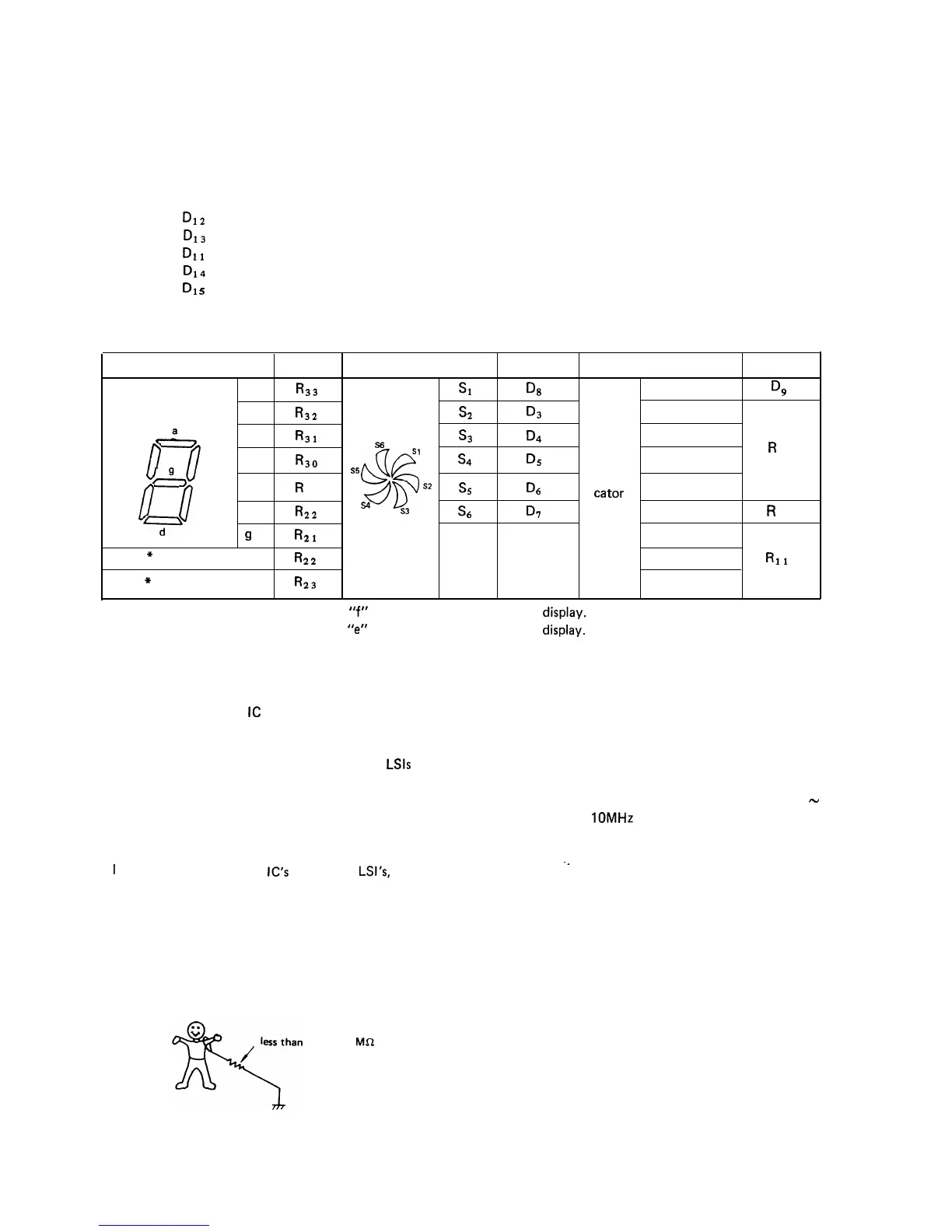
Relations of between Digit and Segment Signal.
The requirements for display are as follows:
1. Specifying digits.
2. Specifying segments.
The following signals are responsible for specifying digits.
1st
digit:
D12
2nd
digit:
D13
Colon digit: DI1
3rd
digit:
D14
4th
digit:
D1
s
5th
digit: Connected to GND.
The following signals are responsible for specifying segments.
Segment
Signal
Segment
Signal
Segment
Signal
character
a
R33
character
Sl
Q3
CONV
D!2
format
b
R32
format
s2
D3
M. LOW
,e,
C
R31
0
l
s6
s3
D4
MED
Sl
f
b
d
R30
&
S5
D
l7
e
R
&@
R
s4
D5
M. HIGH
10
23
Q
Indi-
sz
S5
D6
cator
HIGH
e
C
57
f
R22
4
s4
S3
s6
D7
COOK
R
12
9
R21
MIX
*
Upper colon
R22
MEM
RII
*
Lower colon
R23
AUTO
*Notes 1. The upper colon is connected to
“f”
segment into the fluorescent
display.
2. The lower colon is connected to
“err
segment into the fluorescent
display.
SERVICING
1. Precautions for Handling Electronic Components
This unit uses CMOS
IC
and CMOS LSI in the integral
part of the circuits. When handling these parts, the fol-
lowing precautions should be strictly followed.
Compared to bi-polar IC, CMOS IC and CMOS
LSls
have
extremely high impedance at its input and output ter-
minals. For this reason, it is easily influenced by the
surrounding high voltage power source, static electricity
charged in clothes, etc, and sometimes it is not fully
protected by the built-in protection circuit.
1
n order to protect CMOS
IC’s
and CMOS
LSl’s,
1) When storing and transporting,
thoroughly wrap them in aluminum foil.
Also wrap PW boards containing them in aluminum
foil.
2) When soldering,
ground the technician as shown in the figure and use
grounded soldering iron and work table.
approx. 1
MC2
2. Servicing Tools
Following tools are required when servicing the touch
control panel assembly.
1) Soldering: 30W
(To prevent leaking current, it is recommended to
use a soldering iron with grounding terminal.)
2) Oscilloscope:
Single beam, frequency range: DC
-
10MHz type or more advanced model
3) Checker:
Exclusively designed checker (refer to
“Checker”)
4) Others:
--
Other tools
3. Other Precautions
1) When turning on the power source of the control
unit, remove the aluminum foil applied for preventing
static electricity.
2) Connect the connectors of the indicator and key
units to the control unit taking care that the lead
wires are not twisted.
3) After aluminum foil is removed, take extra care that
abnormal voltage due to static electricity etc. is not
applied to the input or output terminals.
4) Attach connectors, electrolytic capacitors, etc. to PW
board, taking care that all connections are tight.
5) Be sure to use specified components where high pre-
cision is required.
79