DESCRIPTION AND FUNCTION OF COMPONENTS
OVEN LAMP
The oven cavity lamp illuminates the interior of the oven
so that the food being cooked can be examined visually
through the door window without having to open the
door.
COOLING FAN MOTOR
The cooling fan motor drives a blade which draws cooling
air through the oven base. This cooling air is directed
through the air venes surrounding the magnetron and
cools the magnetron assembly. Most of the air is then
exhausted directly through the back vents. However, a
portion of this air is channeled through the cavity to
remove steam and vapors given off from the heating foods.
It is then exhausted at the top of the oven cavity into a
condensation compartment. This fan motor operates
during both microwave and convection cooking.
TURNTABLE MOTOR
The turntable motor rotates the turntable located on the
bottom of oven cavity, so that it works to cook the foods
on the turntable evenly, during both microwave and con-
vection cooking.
THERMISTOR
The thermistor of negative temperature coefficient type.
The temperature in the oven cavity is detected through
the resistance of the thermistor, and then the control unit
causes the heater relay to operate, thus the current to the
heating element is turned ON/OFF.
MAGNETRON THERM0 CUT-OUT
The
therm0
cut-out located on the magnetron assembly,
is designed to prevent damage to the magnetron if an
overheated condition develops in the tube due to cooling
fan failure, obstructed air ducts, dirty or blocked air intake,
etc. Under normal operation, the
therm0
cut-out remains
closed. However,
when abnormally high temperature
within the magnetron approaches a critical level, the
therm0 cut-out will interrupt the circuit to the power trans-
former, and will interrupt the cook cycle. When the
magnetron has cooled to safe operating temperature, the
therm0
cut-out closes and the cook cycle will resume.
COOK RELAY
The cook relay is mounted on the front portion of the
relay chassis.
The coil of the cook relay is energized by the control unit
and relay unit, thereby closing its contacts which provide
a current path to the power transformer.
The cook relay is activated by 12 volts D.C. supplied from
control unit and relay unit.
HEATER RELAY
The heater relay is mounted on the back portion of the
relay chassis.
The coil of the heater relay is energized by the control
unit and relay unit, thereby closing its contacts which
provide a current path to the heating element.
The heater relay is activated by 12 volts D.C. supplied
from the control unit and relay unit.
STOP SWITCH
The stop switch is located on the open device of the
control panel assembly and activated by the door lever.
When the open button is depressed while the oven is in
cook cycle (microwave or convection cooking), the stop
switch contacts open to de-energize the shut-off relays
and cook or heater relay circuit in the control unit and
relay unit.
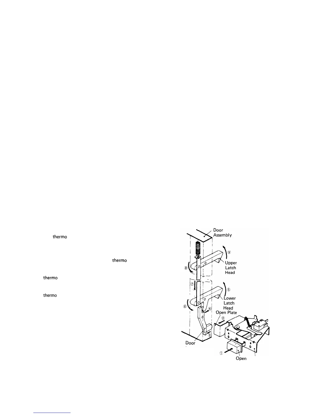
DOOR OPEN MECHANISM
The door can be opened by pushing the open button on
the control panel, refer to Figure 7.
When the open button is pushed, the open plate on the
open device pushes in the door lever on the door, operat-
ing the latch head linkage. The lower and upper latch
heads are moved upward, and are released from the lower
and upper latch hooks.
Now, the door can be opened.
Lever
Open
Open
Button Device
Figure 7 Door Open Mechanism
44