CHECKER
The checker is used when repairing or adjusting the touch
control panel assembly and relay unit.
When connectors coming from the checker are connected
to respective connectors on the control panel components
or relay unit, A.C. power can be supplied from checker
(including relay unit) to control panel components so that
the panel components can be operated, being separated
from the oven circuit electrically.
Use of Checker
a) for repairing
b)
for executing test program
“Test Program” is executed by using the checker.
Connection Method
Control Panel Assembly:
1. Connect the 1 l-pin connector
@
to the control
unit.
2. Connect the
2-pin
connector
@
(for stop switch)
to the control unit.
3. Connect the
5-pin
connector
@
(for damper
switch and thermistor) to the control unit.
Relay Unit:
1. Connect the
2-pin
connector
@
(for stop switch)
to the New control unit.
2. Connect the
5-pin
connector
@
(for damper
switch and thermistor) to the New control unit.
3. Connect the
5-pin
connector
@
to the de-
fective relay unit.
4. Connect the 1 l-pin connector
@
of defective
relay unit to the New control unit.
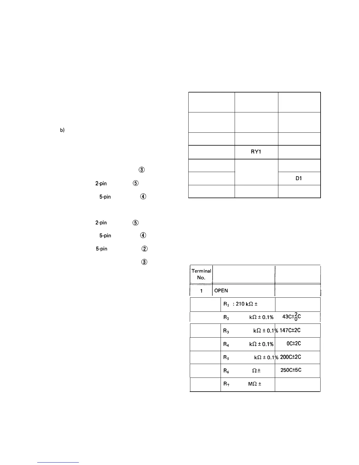
Table 1 shows the relation between the indicator lamps of
the checker, energized relays of the relay unit, and LSI
(I-1 ) signals.
Table 1
INDICATOR
OPERATIONAL SIGNAL
LAMP
RELAY
FROM LSI (l-l)
Oven Lamp
RY2
D2
Turntable Motor
Cooling Fan Motor
Convection Motor
Heater
Cook
Damper
RY3
RYl
Operates at
12V D.C
RY4
D4
DO
D3
Dl
D5
Note: The damper- indicator light is turned on or off by
the damper motor and damper switch in the checker.
Damper indicator light on: Damper is open posi-
tion
Damper indicator light off: Damper is closed posi-
tion
SENSOR DUMMY RESISTANCE
1
Terr:
1
OPEN
ResistanceDisplay Value
1
1
2
Rl
:210
ka2
1% LOC
I
3
R2
: 30
ka*O.l%
43c+
I
4 --
R3
: 6.1
kKZ
+O.l%
147C+2C
5
R4
: 4
kQ*O.l%
11
OCk2C
6
R5
: 1.7
kQ20.1%
200C*2C
7
R(j
: 400
$2
rt
0.1%
25OCX5C
8
R7
:
1
MQ2+
1%
Open judge
80