DAMPER OPERATION
Usually, the damper is open position except during the
convection cooking.
Damper position is set automatically by damper motor,
damper switch, motor cam and damper arm
,lever.
These components are operated according to the signal
that judges the microwave cooking or convection cooking
operation in the control unit.
Microwave Cooking:
Damper is in the open position. Because a portion of
cooling air is channeled through the cavity to remove
steam and vapors given off from the heating foods.
It is then exhausted at the top of the oven cavity into a
condensation compartment.
Convection Cooking:
Damper is in the closed position, so that no hot air will
be allowed to leak out the oven cavity, Figure 8.
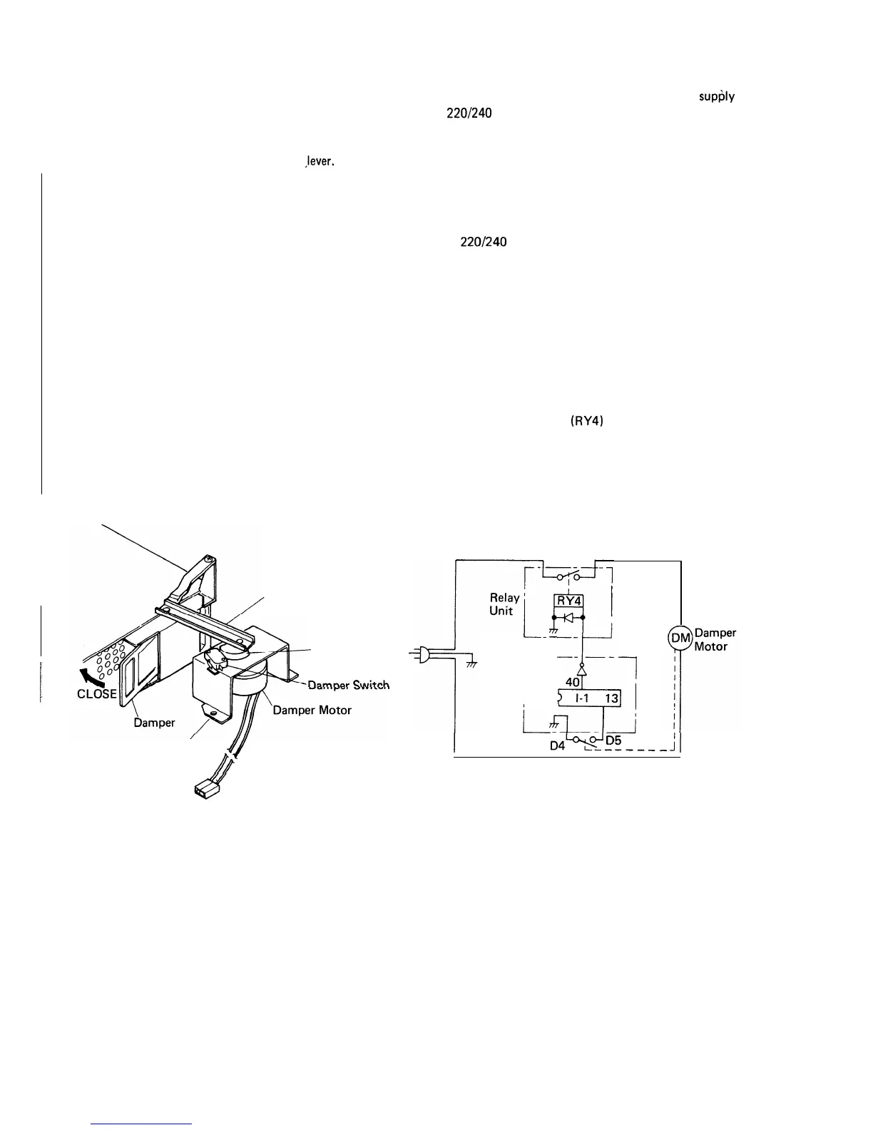
Damper Operation
1. When power supply cord is plugged in:
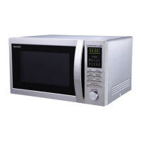
l-l. When power supply cord is plugged in, a signal
is sensed in the control unit, and operates the
shut-off relay (RY4).
Damper Arm Lever
Motor Cam.
nPmnO*
Cwi+t-h
Damper Motor’
J[
Mounting Bracket
11
Figure 12 Damper Operation
l-2. Contacts of shut-off relay (RY4) close and
supljly
220/240
volts A.C. to the damper motor.
The damper motor is energized, opening the damper
door.
l-3. When damper is moved to the open position by the
motor cam and arm lever, damper switch is closed
(ON position).
l-4. The signal of damper switch is re-sensed in the
control unit and shut-off relay (RY4) is turned off.
l-5. The 220/240 volts A.C. to the damper motor is stop-
ped and the motor turns off.
2. When oven is microwave cooking:
Damper is in the open position.
3. When oven is convection cooking:
3-l. Damper motor is energized by touching the con-
vection, temperature and COOK pads.
3-2. When damper is in the closed position (damper
switch is OFF), its signal is sensed by the control
unit, and shut-off relay (RY4) is de-energized.
3-3. The damper is held in the closed position during
the convection cooking operation.
3-4. At the end of the convection cooking, the shut-off
relay (RY4) is energized, and damper is returned to
the open position.
Control
Unit
L-
--
r
--- --
1
I
’
4
40
l-1 13
LEL-i
I
04%
D5
----__
;i
Damper Switch
Figure 13 Damper Motor Circuit
47