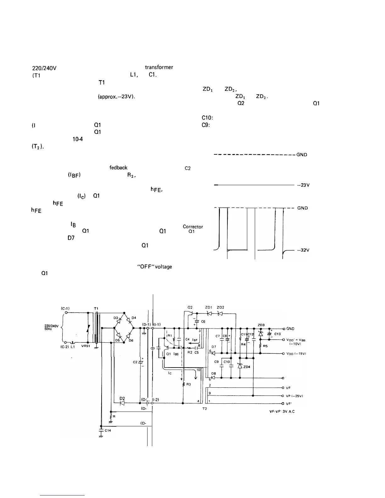
POWER SOURCE CIRCUIT
Power Source Circuit on Relay Unit
220/24OV
AC is applied to the primary of the
tranSfOrmer
(T1
) through a filter circuit consisting of
f-1,
and
Cl.
The secondary output of
Tl
is full-wave rectified by a
bridge circuit of D3 to D6 and smoothed by an electrolytic
capacitor C2 to DC voltage
(approx.
-23V).
DC-DC Converter Circuit
By switching on power supply, the starting base current
(I
BS) flows to transistor
01
through resistor R3 and the
collector currnet (IC) of Ql begins to flow through the
primary winding
10-4
of the DC-DC converter transformer
(T2
1.
The current (IC) varies the magnetic flux of the transformer
core and induces voltage in the base winding 3-8.
The induced voltage is positive
fedback
and produces the
base current (IBF) through resistor
R2,
and the total
current is I B = I BS + I BF.
Therefore, if the current amplification factor is
hFE,
the
collector current
(Ic)
of Ql increases with time until it
reaches
hFE
x lg. When the collector current (I,) reaches
hFE
x IB, IC is saturated and the base winding voltage
induced by the variation of core magnetic flux turns to zero
and accordingly
Ig
turns to zero.
Thus the transistor Ql is rapidly turned off. While Ql is
on, the diodes 07 and D8 on the secondary output circuit
are in reverse polarity and turned off. When Ql is turned
off, the magnetic flux stored in the core begins to reduce
and induces voltage on the secondary output terminals.
At the time, the base winding retains the
“OFF”
v&age
and Ql remains in the “OFF” position.
22Of24OV
50Hz
RELAY UNIT
Tl
+
c2
.-
02
(D-:
ID-
40
(D-
Power source circuit
When variation of magnetic flux turns to zero, the above
steps are repeated and the collector waveform will be as
illustrated in Fig. 19.
As a result, when the VDD voltage increases larger than the
sum of
ZD1
and ZD2, these are turned on and the base
current runs through
ZD1
and ZD2.
By the above, bias of
02
is changed and ON-time of Ql is
controlled, thereby stabilizing the output voltage.
C8 and
ClO:
Voltage smoothing capacitors
C7 and
C9:
c2
Corrector
of
01
-
-
Noise by-pass capacitors
-___--
____
-___----
GND
-23V
Figure 19. Normal Waveform
CONTROL UNIT
a2
ZDl
ZD2
GND
VG I-3OVl
I
T2
W-VP
3v
A.C
DC-DC Converter circuit
Figure 18.
Power Source Circuit and DC-DC Converter Circuit
75