TROUBLESHOOTING GUIDE
This model has the control unit and the separate relay unit,
a power supply for driving the control unit.
Thus if the control panel operates normally when the test
program is run, the relay unit needs to be checked.
The following troubleshooting flow charts are prepared for
both units.
Carry out check in the following order.
Note 1) Check the 1 l-pin connector
(D)
of the relay unit
if the soldering is poor, and the copper foil con-
ductors if they are broken.
2) With the key connectors, manipulate the 1 l-pin
connector
(G)
on the control unit by fingers to
check if the soldering is poor.
3) Check other connectors for poor soldering.
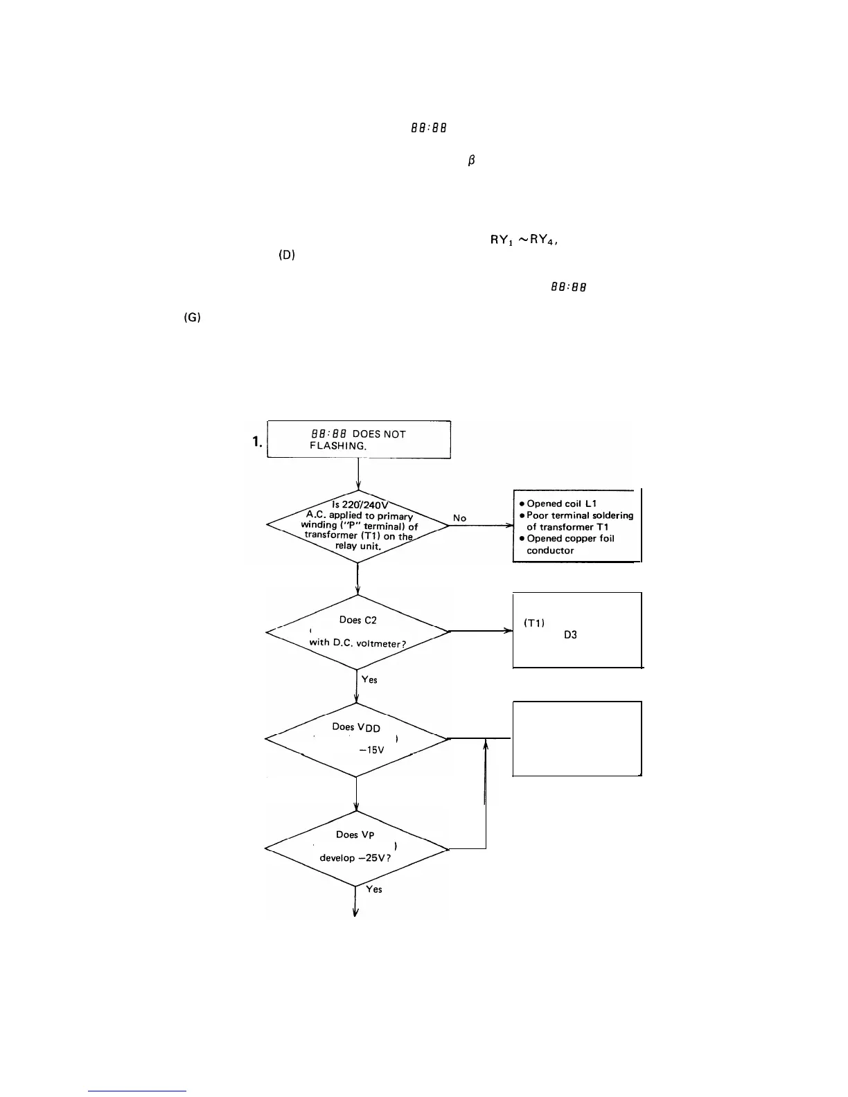
1.
g8:8g
does not flash
A. Check converter circuit
B. Check
fl
circuit
2. All keys fail to transmit input
3. Special matrix group keys fail to transmit input
4. Cook does not start
C. Check damper circuit
5. Shut-off relay RYI
-
RYq,
cook relay or heater relay
does not operate
6. Buzzer does not sound.
7. Faulty power on reset ( BB-88 lights but does not
flash)
8. Faulty display
9. Faulty convection operation
I
Yes
l
Defective transformer
develop approx. 23V
No
(Tl)
*
l
Opened
03
to D6 diodes
l
Faulty C2 or short
terminal (Test Pin)
develop
-15V
?
Yes
No
Defective converter
circuit
+
l
See A. “Check Converter
Circuit” (Next page)
terminal (Test Pin)
No
To page 88
87