Pin No.
Signal
I/O
Description
14
K
11
IN
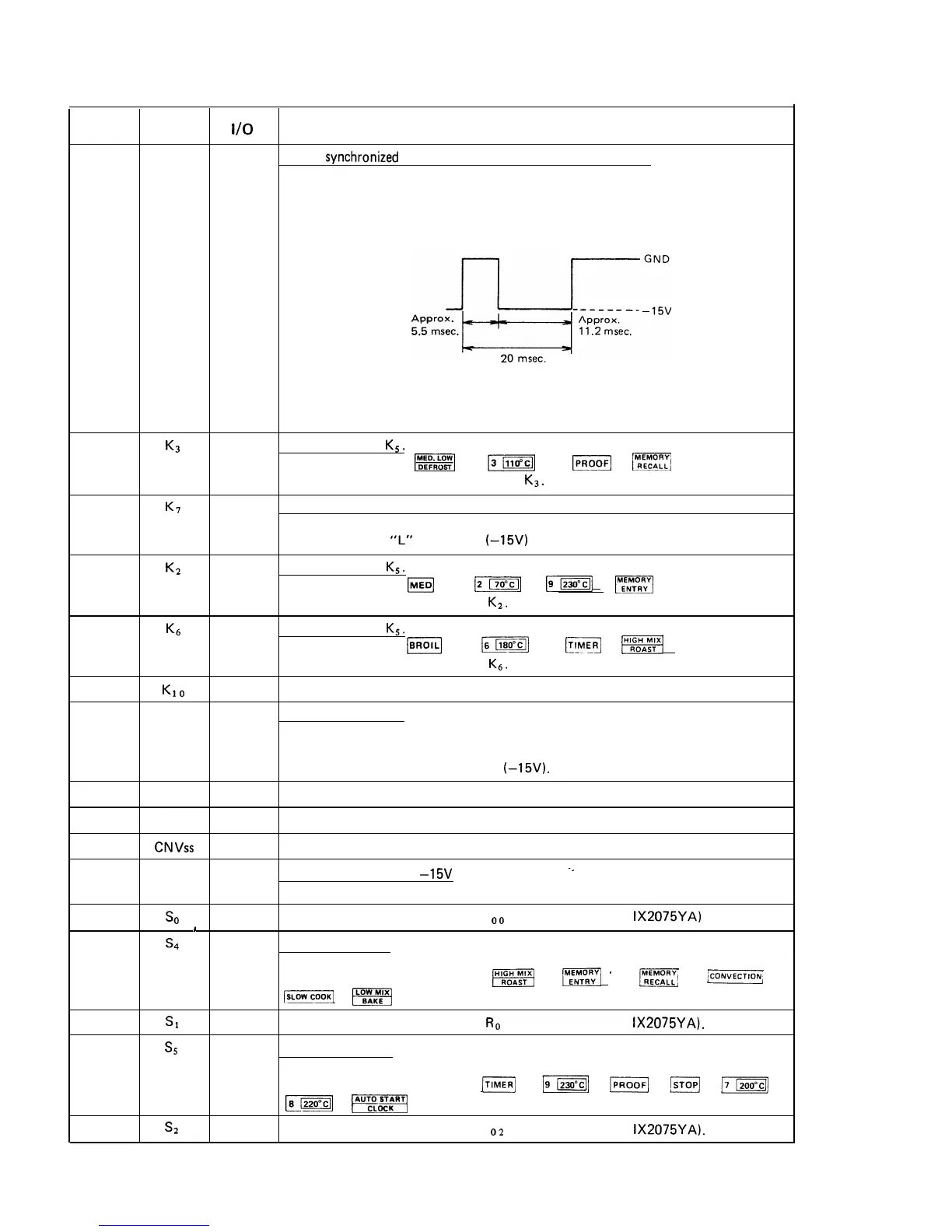
Signal
synchronized
with commercial power source frequency.
This is the basic timing for all time processing.
15
K3
IN
Signal similar to
K5.
When either one of
fggq
, [lllo”cl] ,
pj
or
m
key is touched,
a corresponding signal will be input into
K3.
16
K7
IN
17
K2
IN
To input a signal which communicates the door open/close information to LSI.
Door closed:
“H” level signal (OV)
Door opended:
“L” level signal
(-15V)
Signal similar to
K5.
When either one of
@
,
12
,
-123oDc]j
or
E]
key is touched, a
corresponding signal will be input
K2.
18
K6
IN Signal similar to
Ks.
When either one of
(K]
,
[I1Bo”c11
,
[E]
or
mj
key is touched, a
corresponding signal will be input
K6.
19
ho
IN
20 RESET
IN
Terminal not used.
Auto-clear terminal.
Signal is input to reset the LSI to the initial state when power is supplied.
Temporarily set to “H” level the moment power is supplied, in this time the
LSI is reset. Thereafter set “L” level
(-15V).
21
22
23
24
25
26
27
28
29
vss
INT
CNVss
V DD
so
1
s4
Sl
s5
s2
IN
Connected to GND.
IN
Terminal not used. Connected to GND.
IN
Terminal not used. Connected to GND.
IN Power source voltage:
-15V
-_
Voltage of power source circuit is input.
OUT
Data output port with respect to R
o. terminal of LSI (l-2: IX2075YA)
OUT
Key strobe signal.
Signal applied to touch-key section.
A pulse signal is generated while
w]
,
jMEENMpRRy
*
,
im
,
/~OIUVKTION;
-COOK]
or
1-1
key is being touched.
OUT
Data output port with respect to
R.
1 terminal of LSI (l-2:
IX2075YA).
OUT
Key strobe signal.
Signal applied to touch-key section.
A pulse signal is generated while
m]
,
jT-Gq
,
JPROOF]
,
lSTOPJj
,
j7IZOO”Clj
,
[a1220”Cl]
or
-1
key is being touched.
OUT
Data output port with respect to R
o2
terminal of LSI (l-2: IX2075YA).
65