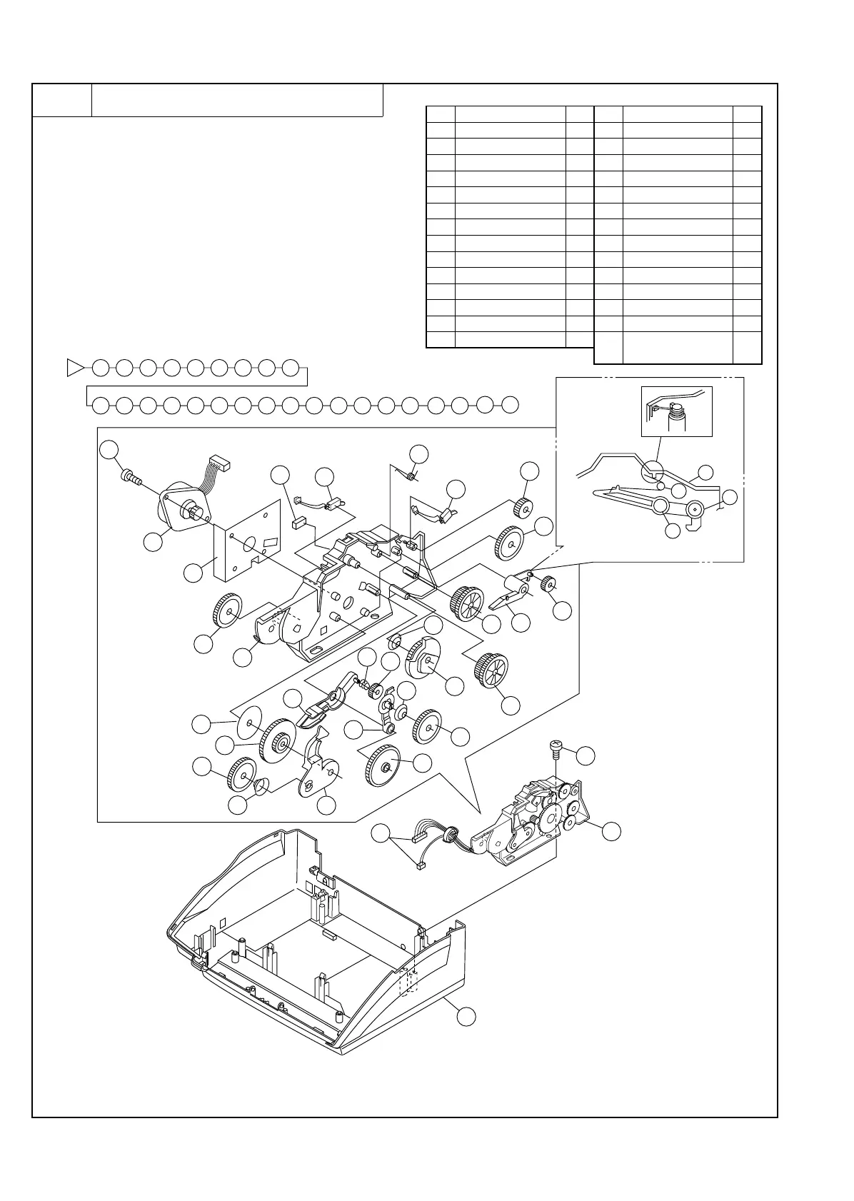
7 Drive system unit
a. Remove the recording paper cover unit, the mechanism unit
according to procedure 1-a.
b. Remove the document guide upper ass’y and document guide
lower ass’y from the mechanism unit according to procedure
2-b.
c. Remove the head frame unit from the mechanism unit accord-
ing to procedure 5-e.
d. Remove the optical system unit from the mechanism unit ac-
cording to procedure 6-c.
e. Remove the drive system unit to the flowchart.
Parts list (Fig. 7)
No. Part name Q’ty No. Part name Q’ty
1 Under cabinet unit 1 15 Planet gear spring 1
2 Screw (M3×12) 1 16 Idler gear 3
3 Connector 2 17 Reduction gear 2
4 Drive system unit 1 18 Planet gear spring 1
5 Screw (M3×6) 1 19 Planet gear lever 1
6 Motor 1 20 Planet gear plate 1
7 Heat sink 1 21 Planet gear 1
8 Reduction gear 1 22 Planet spring 1
9 Change lever spring 1 23 Reduction gear 2
10 Planet gear 1 24 Cam spring 1
11 Change lever 1 25 Idler gear 1
12 Cam A 1 26 Anti vibration sheet 1
13 Detection switch 1 27 Cam spacer 1
14 Planet gear lever 1
28
Drive system mounting
frame
1
3
2
3
4
5
6
7
8
9
10
27
28
11
12
13
14
15
16
17
18
19
20
21
22
23
24
1
5
6
7
9
13
24
8
28
2
4
1
17
17
16
26
18
19
12
11
13
27
10
16
16
15
14
25
23
23
20
21
22
9
11
27
25
26
The tips of spring
are hooked to ribs.
10
Fig. 7
UX-177H
3 – 12