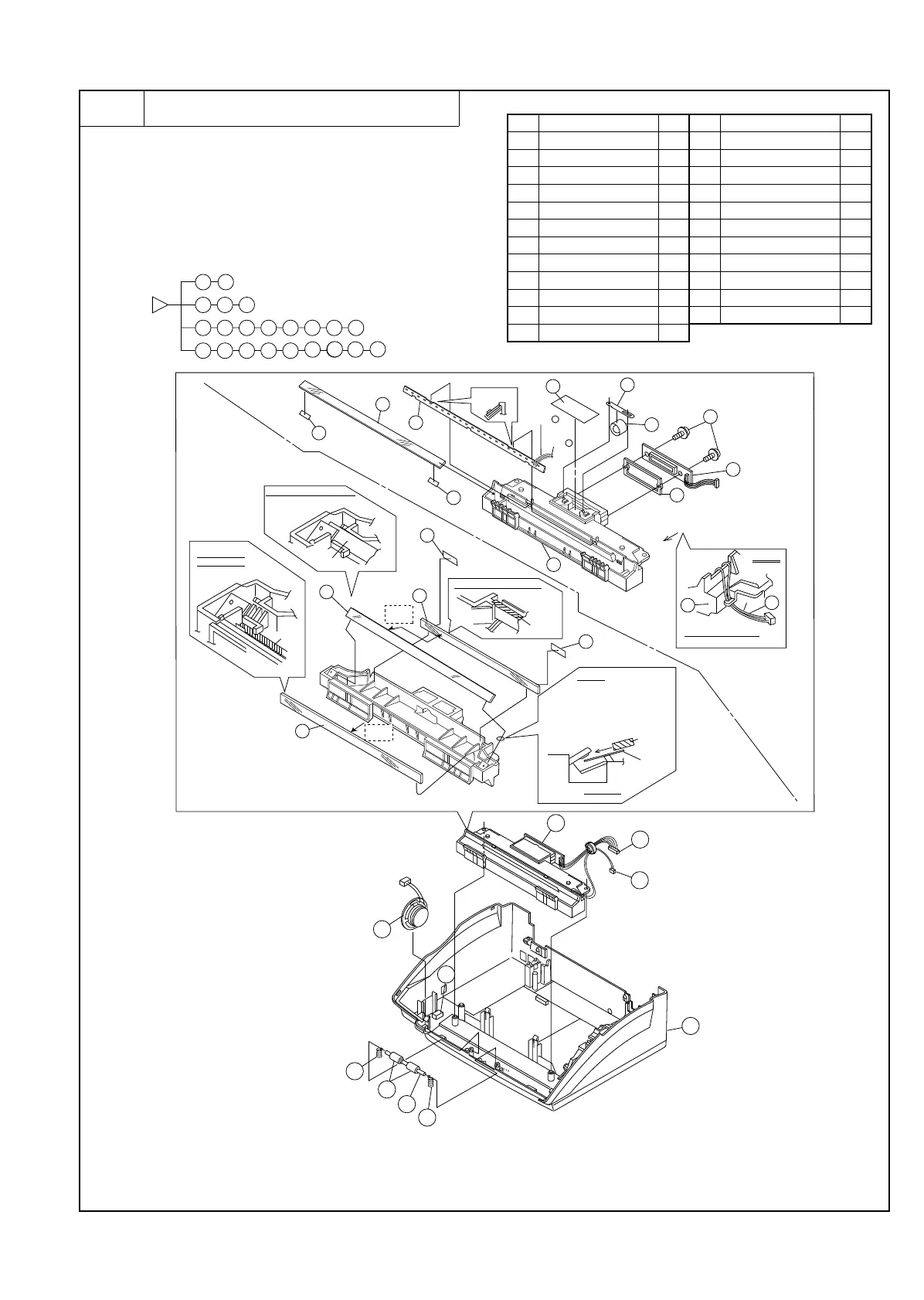
6 Optical system unit and speaker
a. Remove the recording paper cover unit, the mechanism unit
according to procedure 1-a.
b. Remove the document guide upper ass’y and document guide
lower ass’y from the mechanism unit according to procedure
2-b.
c. Remove the optical system unit and speaker to the flowchart.
Parts list (Fig. 6)
No. Part name Q’ty No. Part name Q’ty
1 Under cabinet unit 1 13 Mirror 2 1
2 Pinch roller 2 14 Screw 2
3 Pinch roller shaft 1 15 CCD PWB unit 1
4 Pinch pressing spring 2 16 CCD spacer 1
5 Speaker unit 1 17 Shading sheet 1
6 Optical frame unit 1 18 Lens holding spring 1
7 Connector 1 19 Lens 1
8 Connector 1 20 Shield sheet 3 2
9 Reader glass 1 21 Mirror sheet 2 2
10 LED 1 22 Speaker cushion 1
11 Mirror 3 1 23 Optical frame 1
12 Mirror 1 1
2
3
6
7
8
9
10
14
15
16
17
18
19
20
20
21
23
11
12
13
4
5
22
6
8
22
6
7
8
1
4
5
3
4
2
13
21
21
12
11
23
10
Blue=
Red=
–
14
19
16
A
9
20
20
15
1
A nail locks
Installation condition fisure
(Right and left)
View A
lib
NOTE)
Cable is inserted to lib
(A slack=NG)
Mirror
Installation condition fisure
(Right and left)
Mirror
Mirror
JIG
Sheet
A section
NOTE
1) The one side of mirror is
inserted from a side previous
The opposite side
2) JIG sheet is put or a frame
lid mirror is inserted.
Installation
condition fisure
(Right and left)
Mirror
face of
reflect
face of
reflect
+
18
17
Fig. 6
[Note]
1. Attention the dection to arrow A.
2. Please don’t touch to reflct face when fix the
mirror to optical frame.
3. Check the dust tingerprints and damage when
have a thats case clean by dry cloth.
UX-177H
3 – 11