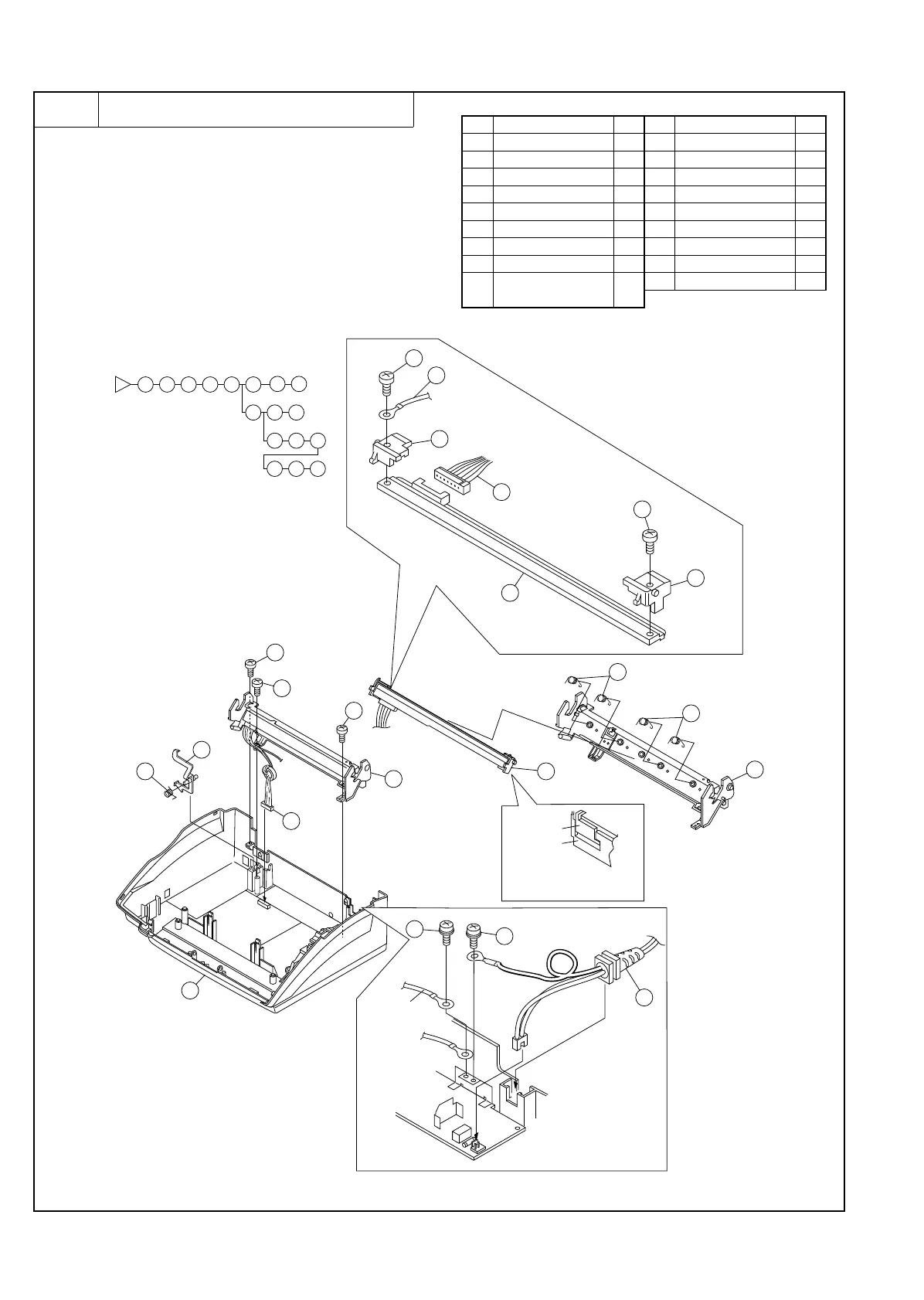
5 Head frame unit
a. Remove the recording paper cover unit, the mechanism unit
according to procedure 1-a.
b. Remove the document guide upper ass’y and document guide
lower ass’y from the mechanism unit according to procedure
2-b.
c. Remove the document guide upper ass’y from the upper cabi-
net ass’y according to procedure 3-c.
d. Remove the upper cabinet ass’y to the flowchart 4-d.
e. Remove the head frame unit from the mechanism unit accord-
ing to procedure.
Parts list (Fig. 5)
No. Part name Q’ty No. Part name Q’ty
1 Under cabinet unit 1 10 Thermal head unit 1
2 Screw (M3×10) 2 11 Head pressure spring 4
3 Screw (M3×12) 1 12 Head frame 1
4 Connector 1 13 Screw (M3×6) 2
5 Screw (M3×6) 1 14 Head earth cable 1
6 Screw (M4×6) 1 15 Head guide left 1
7 Head frame unit 1 16 Head guide right 1
8 Paper sensor lever 1 17 AC cord 1
9
Paper sensor lever
spring
1
18 Thermal head 1
2
3
4
5
6
10
11
12
7
8
9
13
14
15
16
17
18
1
9
1
8
4
7
10
11
11
3
2
2
5
6
17
12
16
13
18
17
13
15
14
note)The head guide should be
securely locked by the click
of the head frame.
Head guide
Head earth
Head frame
Fig. 5
UX-177H
3 – 10