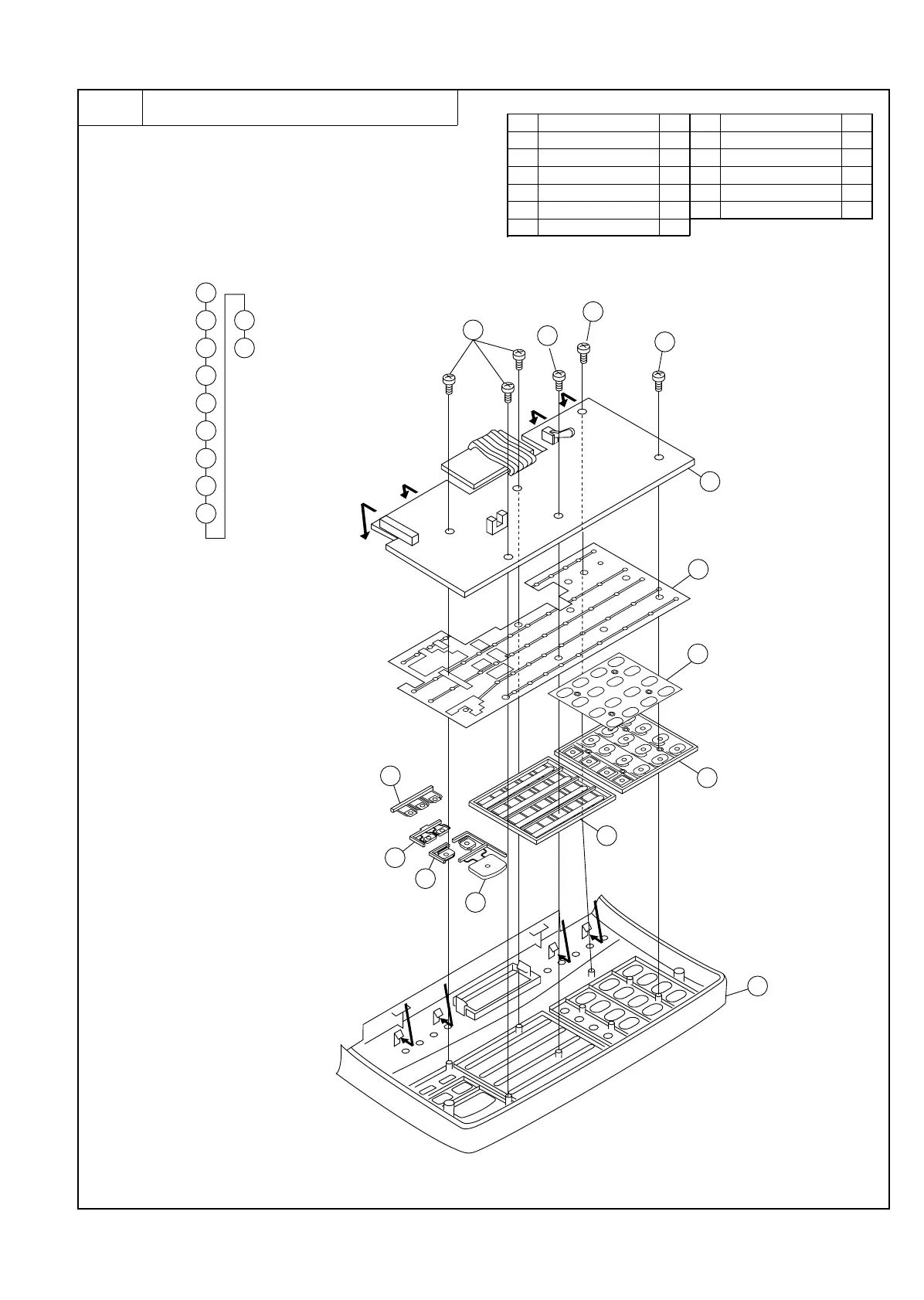
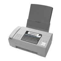
4 Upper cabinet ass’y
a. Remove the recording paper cover unit, the mechanism unit
according to procedure 1-a.
b. Remove the document guide upper ass’y and document guide
lower ass’y from the mechanism unit according to procedure
2-b.
c. Remove the document guide upper ass’y from the upper cabi-
net ass’y according to procedure 3-c.
d. Remove the upper cabinet ass’y to the flowchart.
Parts list (Fig. 4)
No. Part name Q’ty No. Part name Q’ty
1 Screw (M2×6) 6 7 Start key 1
2 Operation panel PWB 1 8 Stop key 1
3 Key sheet 1 9 Volume key 1
4 Rubber sheet 3 10 Mode key 1
5 12 key 1 11 Upper cabinet 1
6 Direct key 1
10
11
1
1
1
1
2
3
4
5
6
7
8
9
1
2
3
4
5
10
11
6
7
8
9
Fig. 4
UX-177H
3 – 9