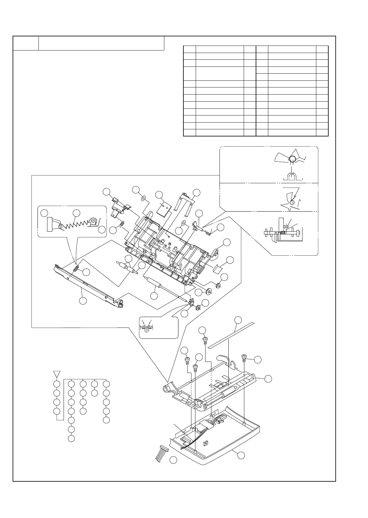
3 Document guide upper ass’y
a. Remove the recording paper cover unit, the mechanism unit
according to procedure 1-a.
b. Remove the document guide upper ass’y and document guide
lower ass’y from the mechanism unit according to procedure
2-b.
c. Remove the document guide upper ass’y to the flowchart.
Parts list (Fig. 3)
No. Part name Q’ty No. Part name Q’ty
1 Upper cabinet unit 1 12 Transfer roller 2 1
2 Panel cable 1 13 Separate spring 1
3
Document guide upper
unit
1
14 Separator plate 1
15 Rubber separator 1
4 Screw (M3×10) 4 16 Feed spring 1
5 Rear sheet 1 17 Document sensor lever 1
6 Panel lock lever spring 1 18 Sensor lever spring 1
7 Panel lock lever 1 19 Pinch roller shaft 1
8 Idler gear 1 20 Pinch roller 2
9 Idler gear 1 21 Ihsulation sheet 1
10 Transfer gear 1 22 Head cover sheet 2
11 Transfer bearing 2 1 23 Document guide upper 1
2
3
4
5
6
10
9
11
12
7
8
22
23
20
19
21
6
13
12
11
10
14
22
22
15
16
18
23
21
20
19
17
21
2
1
3
4
5
7
7
6
9
8
4
4
4
13
14
15
16
17
18
1
Thats bearing
nails must
be lock to
guide.
SP
rib
Front sensor lever mounting
A hook department of SP is hooking
(document sensor lever also
same operation)
Adjust the shaft and bearing
like a picture.
10 Key cable
Fig. 3
UX-177H
3 – 8