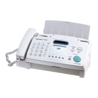
FO-71RA
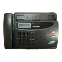
FO-51RA
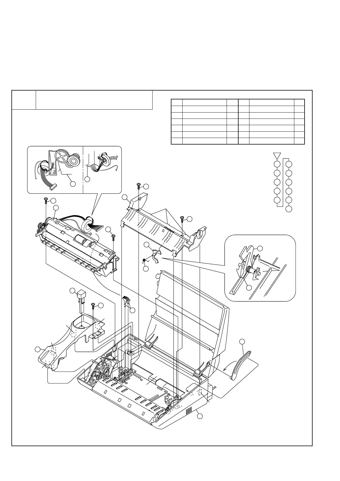
[2] Disassembly and assembly procedures
• This chapter mainly describes the disassembly procedures. For the assembly procedures, reverse the disassembly procedures.
• Easy and simple disassembly/assembly procedures of some parts and units are omitted. For disassembly and assembly of such parts and units,
refer to the Parts List.
• The numbers in the illustration, the parts list and the flowchart in a same section are common to each other.
• To assure reliability of the product, the disassembly and the assembly procedures should be performed carefully and deliberately.
Paper support guide, handset cover
and scanner unit
1
Parts list (Fig. 1)
Fig. 1
3 – 3
Hook
Hook
Hook
Hook
Hook
Control
PWB
Hook
2
2
3
4
5
1
7
8
9
6
12
11
10
10
2
3
4
5
1
6
12
11
7
8
9
10
Fix position of spring
4
5
12
12
No. Part name Q’ty No. Part name Q’ty
1 Mechanism unit 1
2 Screw (3×12) 2
3 Paper support guide 1
4 Paper sensor lever 1
5
Paper sensor lever spring
1
6 Panel stopper 1
7 Screw (3×8) 1
8 Handset cover 1
9 Hook switch lever 1
10 Screw (3×12) 2
11 Connector 2
12 Scanner unit 1
 Loading...