18
XV-Z2000
DT-400
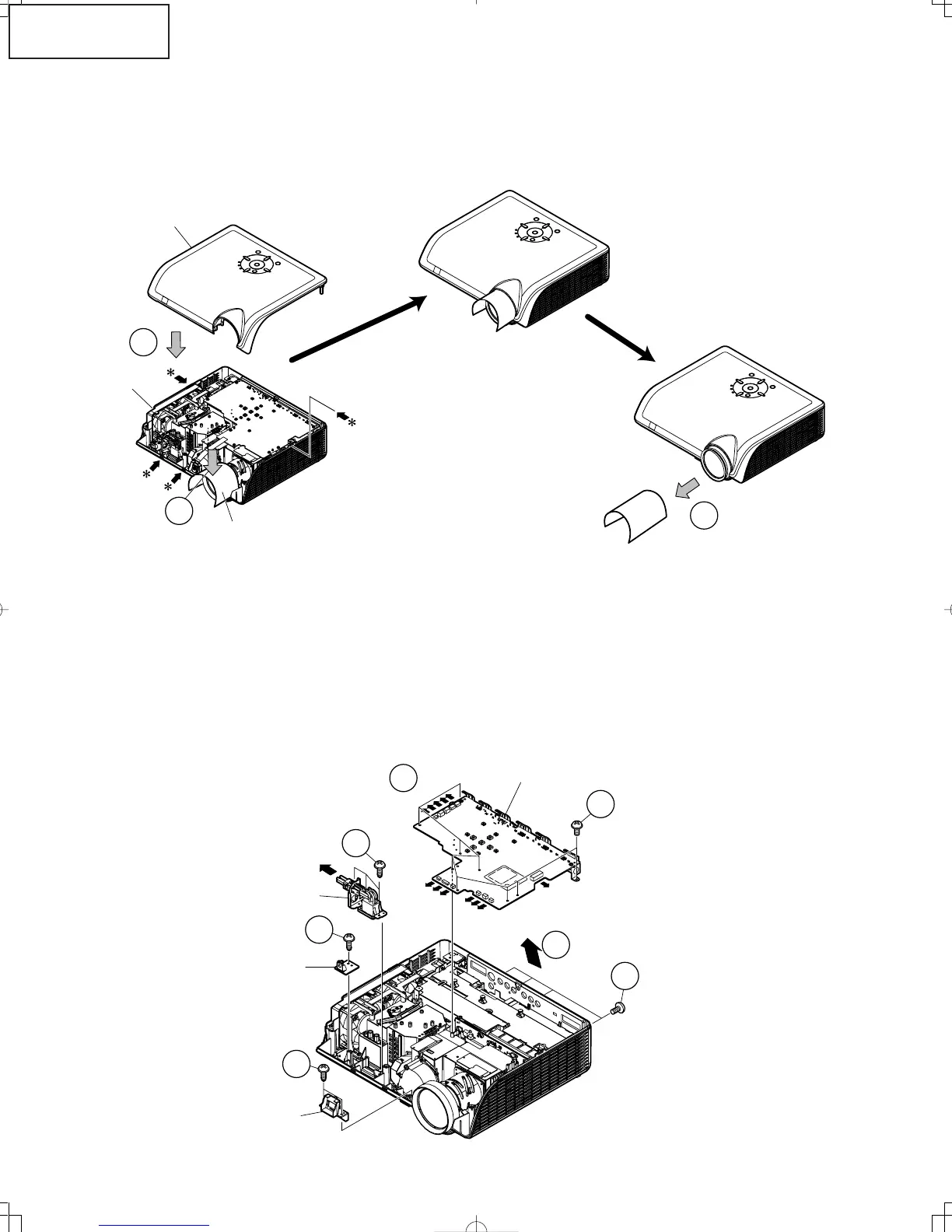
3. Attaching the top body (For the screws to apply, refer back to "2. Removing
the top body".)
3-1. Place the postcard over the lens barrel.
3-2. Place the top body in position. Make sure the four hooks are tightly caught.
3-3. Draw out the postcard.
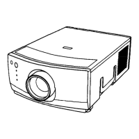
4. Removing the main PWB unit and the peripheral units
4-1. Remove 4 main PWB fixing screws (terminal side).
4-2. Remove 9 main PWB fixing screws.
4-3. Remove 12 connectors from the main PWB.
4-4. Pull out the switch bracket connector and remove 3 fixing screws.
4-5. Remove the fixing screw for the front R/C PWB.
4-6. Remove 2 fixing screws for the button holder unit.
4-7. Lift off the main PWB in an oblique direction from the optical mechanism unit side.
4-1
4-4
4-5
4-6
4-2
4-7
4-3
Main PWB
Button Holder
Switch Bracket
Front-R/C Unit
Top Body
Bottom Body
Thick paper such as postcard
3-2
3-1
3-3