Overview 2
Shield Fire, Safety and Security Ltd.
Shield A-XT Releasing Fire Control Panel - Installation and Operation Manual SEXTCP-OM
Revision E01.00
8 of 127
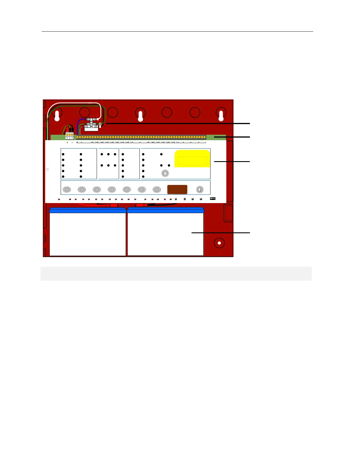
Hardware Features
The figure below illustrates hardware features of the Shield A-XT Releasing Fire Control Panel:
Figure 2-2
Hardware Features
Key Item Description
1 Mains Terminal Block The Mains Terminal Block contains a 1.6 Amp fuse and accepts connections
from the transformer primary and input power connections. Connections from
the primary of the transformer to the Mains Terminal Block are pre-wired at the
Shield factory. Terminals of the Main Terminal Block are designated Line,
Neutral and Ground.
2 Field Terminals Field terminals provide connections for Zones, NACs, Releasing Devices,
Relay Outputs, Status Units and AUX 24V.
3 Fascia The front fascia of the Shield A-XT Releasing Fire Control Panel is
populated with controls and indicators for programming and operating the fire
control panel.
4 Standby-Batteries The Shield A-XT Releasing Fire Control Panel contains two 12 VDC, 7 AH
batteries for operating the fire control panel during primary AC power failure.
7 A/H BATTERY
7 A/H BATTERY
7 A/H BATTERY7 AH Battery
7 AH Battery
L
Low
Pres. Tale
Tell Terminate
Releas e
W/Dog
Reset
Processor
Reset
Exting.
Mon.
Write
Enable
Exting.
ReleaseMode
Man.Rel.Abort
Trbl.Trbl.Trbl.Trbl.Trbl.Trbl.
NAC3NAC1 NAC2Sys.FuseEarth
Trbl.Trbl.Trbl.Trbl.Trbl.
Comms
Low
Batt.
Trbl.
Aux.24V
Trbl.
CPU
Mains
Fail
(+1)(+10)
Enter System ModeSelectModeReset Lamp Test
(+100)
Silence/Sound
Alarm
On Test/Disabled
Test Mode On
General
Disablement
System Trouble
Buzzer Silenced
2nd Stage Output
Extract F an On
Abort Activated
Releasing Trouble
Silence
Buzzer
Enable Access
EXTRACT
SWITCH
REL PRES.
SWITCH
LOW P.EXTING.ABORT
RELEASE
MAN.
SELECT
MODE2ND STAGE1ST STAGENAC3POWERDATA
STATUS UNITS
REMOTE
CONTROL
AUX
24V
CNONOCNCNOCNC
ZONE 3
E
ZONE 1 ZONE 2NAC2NAC1
RSTR0V SIL AL F LT NOCNCNOCNCNOCNC
FIRE RELAYLOCAL FIRETROUBLE RELAY
24V DC
Power On
General System Status Fire In Zone
123
Zone Trouble/
Disablements/
Supervisory
Releasing Status
Fire
Delay On
NAC Trouble/
Disabled
Power Trouble
General Trouble
Manual Release
Extinguishant
1st Stage Output
Release
Imminent
Auto &
Manual
Manual
Only
Extinguishant
Released
Low
Pressue
1st Stage
Activated
Pull Down - Push Button
Manual
Extinguishant Release
FUSE
N
1
2
3
4