Installation 3
Shield Fire, Safety and Security Ltd.
Shield A-XT Releasing Fire Control Panel - Installation and Operation Manual SEXTCP-OM
Revision E01.00
24 of 127
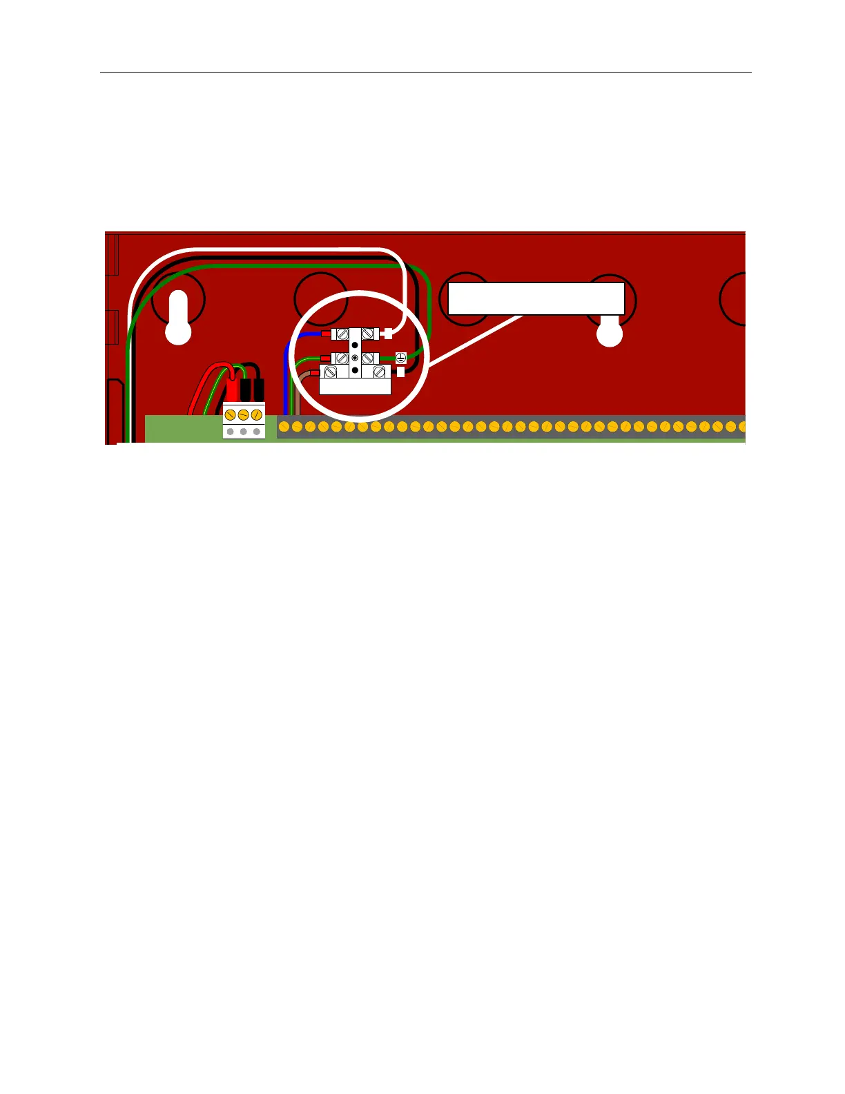
The figure below illustrates supervised connections at the mains terminal block for the Line (L), Neutral (N) and
Ground of the AC power source.
Figure 3-4
Supervised Connections At The Mains Terminal Block
Reference Appendix A, Specifications for the wire-gage requirements of these connections.
Standby-Battery Cabling
Perform the installation only after calculations have been completed for selecting a suitable battery size.
Battery standby-hours are dependant on battery capacity and loading of the FACP system.
To install the replacement standby-batteries:
Do not connect the two batteries in parallel. A parallel connection will not provide the 24 volts required for
operating the Shield A-XT Releasing Fire Control Panel in a standby condition.
The recharging circuit of the power supply charges batteries to a maximum voltage of 27.6 VDC @ 700 mA.
The fire control panel accepts sealed-lead-acid rechargeable-batteries with a maximum capacity of 7 AH.
The maximum current drawn from the batteries is 2 Amps when the main power source is disconnected.
Observe polarity when connecting the leads of the standby-batteries to the fire control panel. Improper connections
to the standby-batteries could damage the fire control panel and severely limit overall fire control panel operation.
Connect two standby-batteries to the power supply in series.
1 Place standby-batteries at the bottom of the Shield A-XT Releasing Fire Control Panel cabinet.
2 Connect the black battery-lead to the negative terminal of Battery 2.
3 Connect the red battery-lead to the positive terminal of Battery 1.
4 Connect the jumper-lead from the negative terminal of Battery 1 to the positive terminal of Battery 2.
5 Mark a “placed into service” date” on Battery 1 and Battery 2.
L
FUSE
N
Mains Terminal Block