Specifications A
Shield Fire, Safety and Security Ltd.
Shield A-XT Releasing Fire Control Panel - Installation and Operation Manual SEXTCP-OM
Revision E01.00
69 of 127
NAC outputs on the Shield A-XT Releasing Fire Control Panel are load dependant and are limited to a maximum
current load of 500 mA. The releasing output on the Shield A-XT Releasing Fire Control Panel is load dependant
and is limited to a maximum current load of 1000 mA.
Total standby-current of these loads must draw less than 236 mA to maintain continuous standby operation for
twenty-four hours followed by five minutes of alarm.
Current loading calculations do not include the combined IDC currents of the Shield A-XT Releasing Fire Con-
trol Panel. These combined IDC currents are negligible in comparison to fire control panel, ancillary device and NAC
currents of the Shield A-XT Releasing Fire Control Panel and are therefore excluded from the current loading
calculation.
Ground Trouble Indication
A ground trouble indication occurs when a minimum of 30K Ohms exists between earth-ground and the following
VDC terminals of the fire control panel:
• AUX 24V
• POWER, STATUS UNITS
• NAC 1, NAC 2 and NAC 3
• ZONE 1, ZONE 2, ZONE 3
• MODE SELECT
• MAN RELEASE
•ABORT
• REL. PRES. SWITCH
•EXTING.
•LOW P. SWITCH
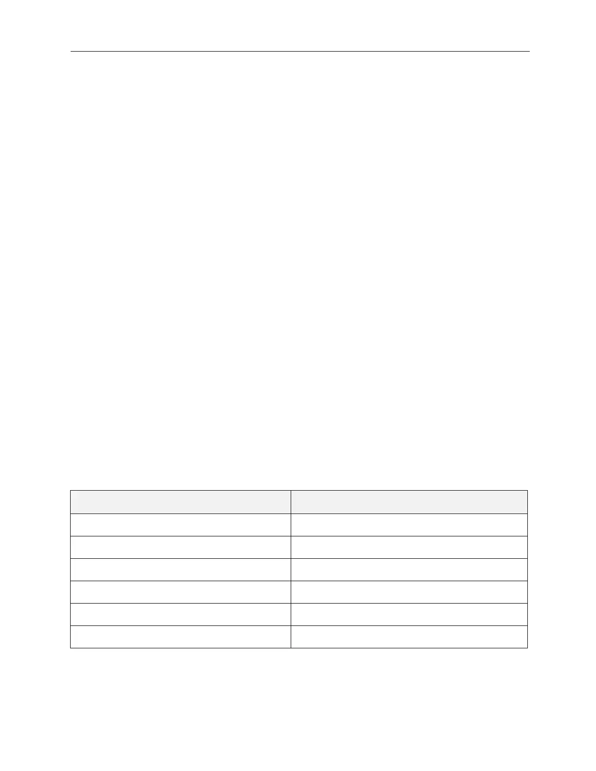
Field Wiring
The following specifications identify the range of acceptable wire gages for field wiring, battery and power
connections:
Terminal Wire Range
AUX 24V 14 - 18 AWG
REMOTE CONTROL No Connection (NC)
DATA - STATUS UNITS
14 - 18 AWG
POWER - STATUS UNITS 14 - 18 AWG
NAC 1, NAC 2 14 - 18 AWG
ZONE 1, ZONE 2, ZONE 3 14 - 18 AWG