Specifications A
Shield Fire, Safety and Security Ltd.
Shield A-XT Releasing Fire Control Panel - Installation and Operation Manual SEXTCP-OM
Revision E01.00
70 of 127
Battery and Line Connections
Battery leads are provided in the cabinet for recharging the standby-batteries. One end of the battery leads are
permanently connected to the power supply of the Shield A-XT Releasing Fire Control Panel. The opposite end
of the battery leads connect to terminals of the standby-batteries.
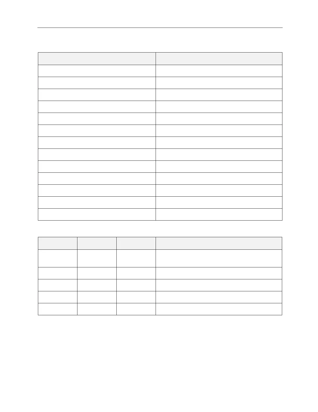
Terminal Wire Range
2ND SOUNDER 14 - 18 AWG
1ST STAGE 14 - 18 AWG
2ND STAGE 14 - 18 AWG
MODE SELECT 14 - 18 AWG
MAN RELEASE 14 - 18 AWG
ABORT 14 - 18 AWG
REL PRES SWITCH 14 - 18 AWG
EXTING. 14 - 18 AWG
LOW PRES. SWITCH 14 - 18 AWG
EXTRACT 14 - 18 AWG
TROUBLE RELAY 14 - 18 AWG
LOCAL FIRE 14 - 18 AWG
FIRE RELAY 14 - 18 AWG
Designation Terminal Wire Range Description
Battery
Connection
+ Red lead Positive connection for the Standby-batteries
- Black lead Negative connection for the Standby-batteries
AC Power L 14 AWG Line connection
N 14 AWG Neutral connection
E 14 AWG Ground connection