Specifications A
Shield Fire, Safety and Security Ltd.
Shield A-XT Releasing Fire Control Panel - Installation and Operation Manual SEXTCP-OM
Revision E01.00
68 of 127
Rechargeable Battery Circuit
Standby-Battery Loads
Standby-batteries of the Shield A-XT Releasing Fire Control Panel are rated for 7 AH of operation. The standby-
batteries can provide an operating duration of twenty-four hours followed by five minutes of alarm when the standby
current does not exceed 236 mA.
Standby and alarm current of the Shield A-XT Releasing Fire Control Panel can include all or part of the
following loads:
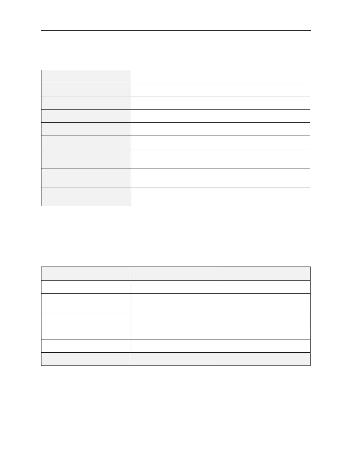
Standby-Battery Type 12 VDC, 7 AH, sealed lead acid
Standby-Battery Charging Two standby batteries wired in series
Charge Current 700 mA maximum
Output Current 0 - 2 Amps
Battery Fuse 3.0 A, 250 VAC, slow-blow, (.2 x 0.787401)” ((5 x 20) mm)
Battery Charge Voltage 27.6 VDC current limited at 700 mA maximum
Current Draw From Battery In
Mains Fail, Standby, Not in Alarm
100 mA with buzzer sounding
Maximum Current Draw of FACP,
In Alarm
620 mA (Current does not include loads from NACs, Solenoid,
Status Units, Ancillary Boards and Auxiliary equipment)
Maximum Current Draw
From Batteries
2 Amps
Loads Standby Current Alarm Current
FACP 100 mA 620 mA
Status Unit 50 mA (per unit) 83 mA average per unit (max)
94 mA peak per unit (max)
Ancillary Board 16 mA (per board) 175 mA per board (max)
NAC Outputs 0 mA (per NAC output) 500 mA (per NAC output)
Releasing Output 0 mA 1000 mA
Total Maximum Current 236 mA 2000 mA