Supplementary Devices 6
Shield Fire, Safety and Security Ltd.
Shield A-XT Releasing Fire Control Panel - Installation and Operation Manual SEXTCP-OM
Revision E01.00
61 of 127
Connecting Power
The Ancillary Board requires 24 VDC to operate. Provide this 24 VDC power from the AUX 24V or the STATUS
UNIT, POWER terminals of the Shield A-XT Releasing Fire Control Panel.
The total current obtained from connecting multiple Ancillary Boards and Status Units to the Shield A-XT Releasing
Fire fire control panel must be below the maximum ratings of the AUX 24V or STATUS UNIT, POWER outputs.
If the total current required by the connection exceeds these maximum fire control panel ratings then a separate power
source must be used that is capable of providing this current level.
Reference Appendix A, Specifications for ratings of the AUX 24V, STATUS UNIT and POWER terminals.
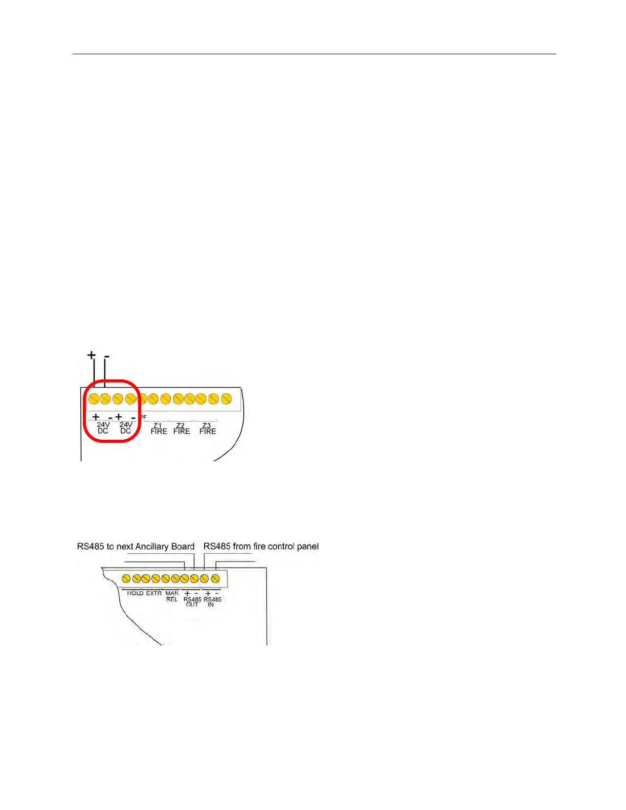
Two-sets of terminals are provided for 24 VDC wiring on the Ancillary Board. Connect incoming 24 VDC wiring to
one set of the two terminals. Connect out-going 24 VDC wiring to the remaining set of two-terminals. Out-going
wiring of the Ancillary Board can include additional Ancillary Boards or Status Units.
24 VDC Terminals
The figure below illustrates two-sets of 24 VDC terminals on the Ancillary Board:
Figure 6-5
24 VDC Terminals
Connecting Data
The figure below illustrates RS485 data connections of the Ancillary Board:
Figure 6-6
RS485 Data Connections of the Ancillary Board