Installation 3
Shield Fire, Safety and Security Ltd.
Shield A-XT Releasing Fire Control Panel - Installation and Operation Manual SEXTCP-OM
Revision E01.00
27 of 127
The figure below illustrates a single detector connection on the zone terminals of the Shield A-XT Releasing
Fire Control Panel:
Figure 3-6
Single Detector Connection
Supervised Inputs
Supervised inputs of the Shield A-XT Releasing Fire Control Panel are Class B, Style C Initiating Device Cir-
cuits (IDC).
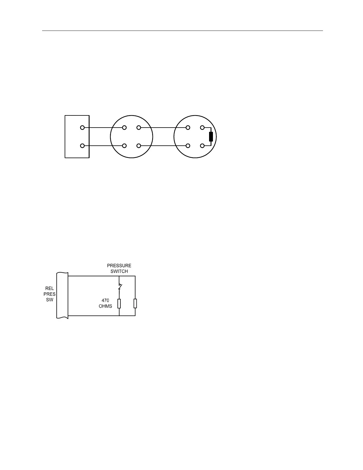
Supervised inputs include the field terminals of MAN RELEASE, ABORT, REL. PRES. SWITCH and LOW P.
SWITCH. These inputs are supervised for open-circuit, short-circuit and ground-fault conditions.
Circuits operating on these terminals require a 6.8K Ohm EOL resistor, SEOLR-6.8 and a nominal, 470 Ohm trigger
resistor, SEOLR-470.
The figure below illustrates a typical supervised input connection on terminals of the A-XT Releasing Fire
Control Panel.
Figure 3-7
Supervised Inputs
NAC 1
( + )
( - )
( + )
( - )
( + )
( - )
Polarized
Annunciator
Polarized
Annunciator
10K Ohm
EOL Resistor
SEOLR-10
6.8K Ohm
EOL Resistor,
SEOLR-6.8