Installation 3
Shield Fire, Safety and Security Ltd.
Shield A-XT Releasing Fire Control Panel - Installation and Operation Manual SEXTCP-OM
Revision E01.00
32 of 127
The Shield A-XT Releasing Fire Control Panel operates only Shield authorized solenoid releasing valves.
Reference Appendix B, Equipment List for a list of Authorized Releasing Valves.
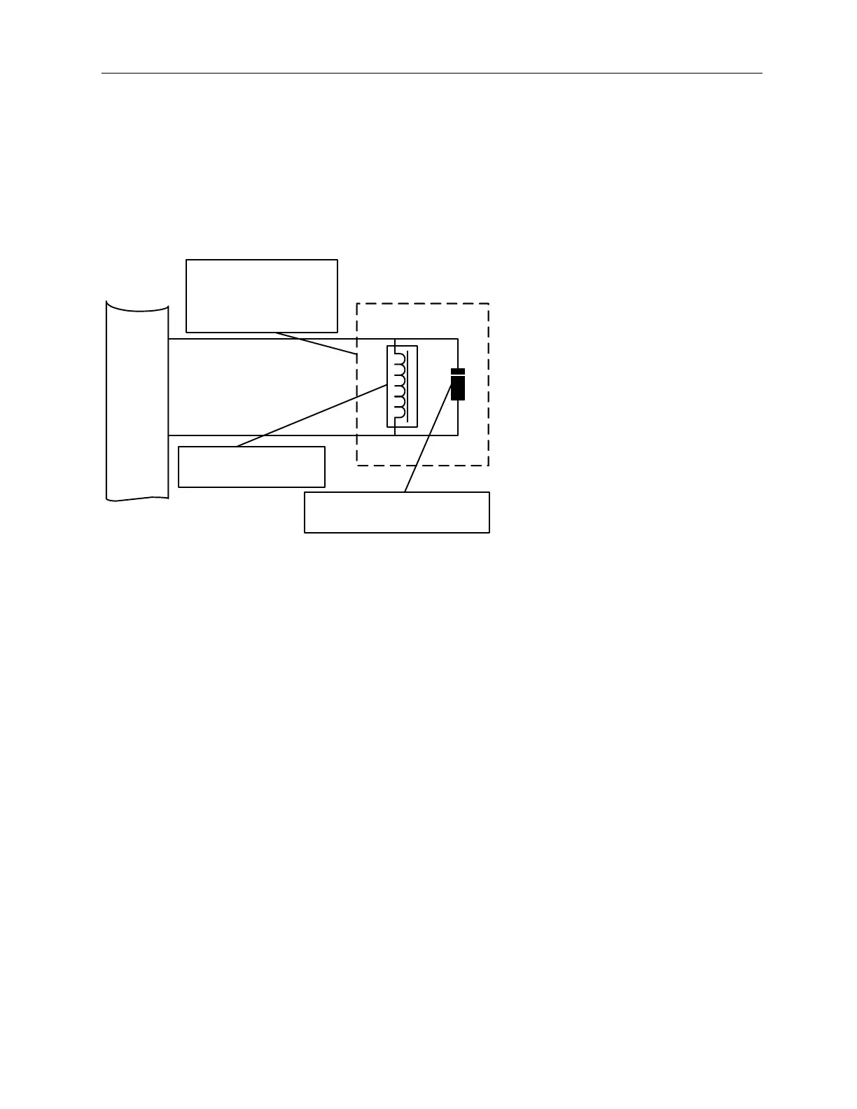
The figure below illustrates an example of the wiring for the releasing solenoid:
Figure 3-11
Releasing Solenoid Wiring
Monitoring Circuit
All control panels are supplied with end of line diodes for the connection of solenoids. It should not be necessary to
adjust the trouble monitoring circuit in this configuration, unless the panel fails to report a short circuit trouble when
tested by shorting the end of line device.
Halon 1301
If the system is intended for Halon 1301 the user must install a mechanical manual release.
Manual Release
• If abort is activated first, the manual release overrides the abort function.
• If manual release is activated first, the abort function overrides the manual release.
The Manual Release Switch shall be marked “Manual Release” or “Manual Dump” at its installed location.
The Manual Release can override an activated Abort condition.
+
-
+
-
EXTING.
EOL Diode 1N504-G, SEOLD-504
band end to ( + )
Solenoid Releasing Valve
and EOL Diode 1N504-G,
SEOLD-504 connected in
the same junction box
Solenoid Releasing Valve
30 Ohms minimum