25
e
HC1 Output during alarm action of either heater 1 break/loop.
f
HC2 Output during alarm action of either heater 2 break/loop.
g
STPS Step signal Ouput for 1 second each time step in program control execution is completed.
h
PTNS Pattern signal Ouput for 1 second each time pattern in program control execution is completed.
i
ENDS Program end signal Output for 1 second when program control execution is completed.
j
HOLD Hold signal Output when holding (temporary halt of program) during program control.
k
PROG Program signal Output when set to program mode.
l
U_SL Up slope signal Output during up slope step execution during program control.
⑪ D_SL Down slope signal Output during down slope step execution during program control.
8-2. Heater break/loop alarm
Heater break/loop alarm can be used only in control output Y (contact) or P (SSR drive voltage output).
Heater break/loop alarm becomes effective if CT input or event output is equipped.
Heater break alarm outputs an alarm if the current value detected by CT when control output is ON is lower than the setting.
Heater loop alarm also outputs an alarm if the current value detected by CT when control output is OFF is higher than the setting.
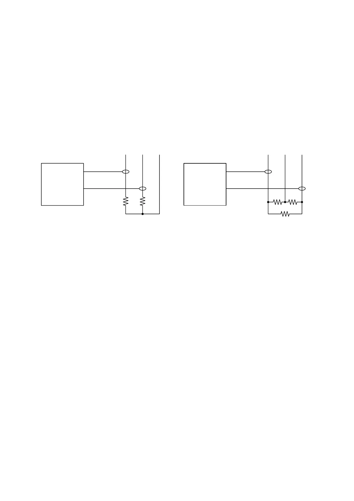
In the SRS10 series, 2 points of CT input is equipped if the CT input option is selected.
Any break of 2 heating stages control heater or three-phase heater can be detected by using two CT.
For 2 heating stages For three-phase
8-3. P.I.D.
(1) P (proportional action)
Sets percentage at which control output varies for measuring range. The size of control output varies according to ratio of PV value
to SV value.
Slight proportional band variation results in strong proportional action. If it is too slight, control vibrates and the results of control
are similar to ON-OFF action.
(2) I (Integral time)
Function that corrects offset (constant deviation) produced by proportional band. The longer the integral time, the weaker the
corrective action and the shorter the time, the stronger the action is, but control may vibrate due to integral hunting.
(3) D (Derivative time)
Enhances stability by estimating change in control output and suppressing integral overshoot.
The longer the derivative time, the stronger derivative action is, but control results may be similar to vibration.
(4) MR (Manual reset)
With PID action “I” is automatically offset, but if “I” is OFF, it is not offset. If so, it can be offset by manually increasing/
decreasing output. This is called “manual reset.”
(5) SF (Target value function)
This function determines the strength of the overshoot preventing function when operating expert PID.
Expert PID suppresses overshoot by conducting operation for predicting and canceling the amount of overshoot by referring to
the PID value and the variation of PV value when it reached the targeted setting value (SV) (or the proportional band).
Target value function is effective only when there is an integral operation (PI, PID operation).
SF= OFF: Expert PID does not function and normal PID operates.
SF= 1.00: Minimize overshoot for expert PID contronl.
SF→ Small: Overshoot preventing function works limitedly.
SF→ Large: Overshoot preventing function works fully.
8-4. Control output
(1) Lower limit and higher limit setting limiter
① Output limiter limits minimum and maximum values of control output and helps securing minimum temperature and
suppress control overshoot.
② Lower limit value is given priority for output limiter setting. If minimum value is set above the higher limit value, the
higher limit value forcibly becomes the lower limit value + 1%.
Higher limit value cannot be set less than lower limit value + 1%.
CT1
CT2
SRS10 Series
CT
CT
Heater
Heater
CT1
CT2
Heater
SRS10 Series
Heater Heater
CT
CT
 Loading...
