5
3-2. Mounting
CAUTION
In order to maintain safety and function, do not remove the case from the controller.
If the case of the controller has to be removed for replacement/repair, contact your nearest Shimaden agent.
c
Cut a hole for mounting the controller in the panel by referring to external dimentions and panel cutout in section 3-3.
d
The panel thickness should be 1.0 – 3.5 mm.
e
The controller is provided with tabs for mounting. Insert as is from the front surface of the panel.
f
Controllers of the SRS10 Series are designed for mounting on the panel. Be sure to mount on the panel.
g
If mounted in series, provide ventilation so ambient temperature does not exceed 50°C due to temparature rise caused by heat
generation.
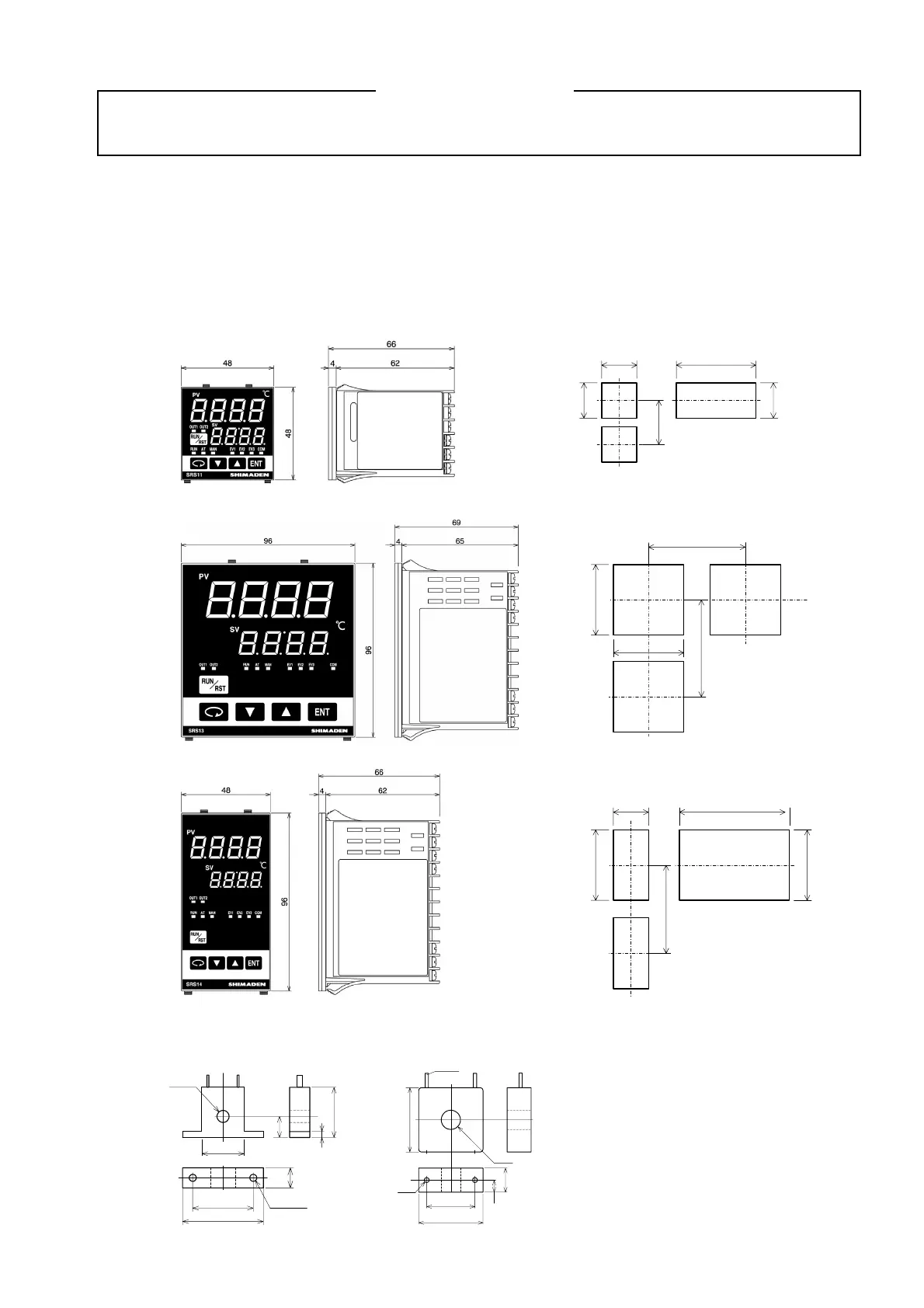
3-3. External dimensions and panel cutout
SRS11
SRS13
SRS14
External dimensions of current detector for heater break alarm (CT)
0 ~ 30A (CTL-6-S) 0 ~ 50A (CTL-12-S36-8)
30
40
25
10
5.8
2- 3.5
21
10.5
3
30
40
40
15
7.5
12
2-M3
2.36
Unit: mm
(48×N-3)
+1.0
-0
45
Min. 60
45
+0.6
-0
45
If mounted horizontally
N=Number of units
Panel cutout
+0.6
-0
+0.6
-0
Unit: mm
Min. 130
92
+0.8
-0
92
+0.8
-0
Min. 130
Panel cutout
Unit: mm
Min. 130
45
+0.6
-0
(48×N-3)
+1.0
-0
92
+0.8
-0
92
+0.8
-0
If mounted horizontally
N=Number of units
Panel cutout
Unit: mm
 Loading...
