28
(2) Conditions that cancel soft start
c
When soft start time has elapsed normally.
d
When output values of soft start are higher than PID operation output values.
e
When soft start time is changed to OFF.
f
When switched to manual mode.
g
When AT (auto tuning) is executed.
h
When P (proportional band) is changed to OFF.
i
When control output characteristics are changed.
j
When in standby mode.
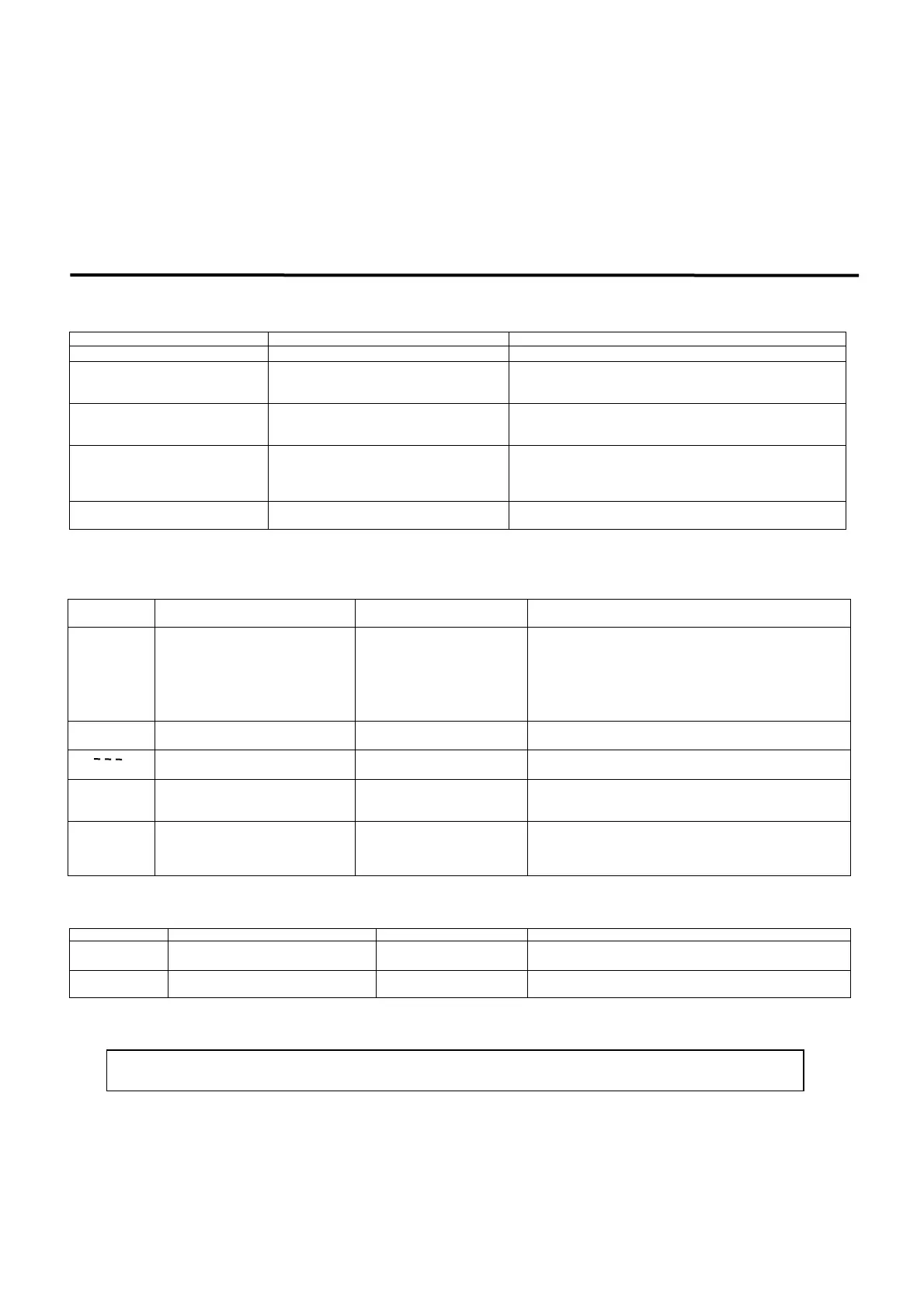
9. Causes and remedy of trouble and errors
9-1. Causes and remedy of trouble
Problem Cause Remedy
c
Error message is displayed.
See “Causes and remedy of errors.” See “Error Codes, Causes and Remedies.”
d
Displayed measured value (PV) seems to
be incorrect.
c
Set measuring range code is different from that of
input sensor / input signal.
d
Erroneous wiring to input terminals of sensor.
c
Check if set measuring range code is correct for input signal.
d
Cortect wiring to input terminals of sensor.
e
Front panel display goes off and does not
function.
c
Problem with power supply and/or wiring
connection.
d
Something is wrong with the instrument.
c
Inspect power supply / wiring connections and check wiring.
d
Inspect, repair or replace the instrument.
f
Keys do not work.
c
Key lock is in effect.
d
Communication is set to Com during
communication.
e
Something is wrong with the instrument.
c
Cancel key lock.
d
Set communication to local (Loc).
e
Inspect, repair or replace the instrument.
g
ON-OFF action of control output is too
fast.
c
ON-OFF “hysteresis range is too narrow. ”
c
Widen ON-OFF “hysteresis range. ”
9-2. Causes and remedy of errors
(1) Abnormal measured input
Screen
display
Problem Cause Remedy
(HHHH)
Higher limit scaleover
c
Break in thermocouple input
wiring.
d
Break in R.T.D. input A wiring.
e
Input measured value exceeded
higher limit of measuring range
by 10%.
c
Check thermocouple input wiring for possible break. If there is
nothing wrong with wiring, replace thermocouple.
d
Check R.T.D. input A terminal wiring for possible break.
If there is nothing wrong with wiring, replace R.T.D.
e
For voltage or current input, check the measurement signal
transmission unit.
Check if set measuring range code is correct for input signal.
(LLLL)
Lower limit scaleover
Input measured value fell below lower
limit of measuring range by 10%.
Check for measurement input wiring for reverse polarity or possible
break.
(b- - -)
Break in R.T.D. input wiring
c
Break in B wiring
d
Multiple break in ABB wiring
Check R.T.D. input ABB terminal wiring for possible break. If there
is nothing wrong with wiring, replace R.T.D.
(CJHH)
Higher limit scaleover of cold junction (CJ)
of thermocouple input
Ambient temperature has exceeded
80°C.
c
Reduce ambient temperature to the level provided in the environment
conditions for the product.
d
If ambient temperature has not exceeded 80°C, examine the controller.
(CJLL)
Lower limit scaleover of cold junction (CJ)
of thermocouple input
Ambient temperature has fallen
below -20°C.
c
Raise ambient temperature to the level provided in the environment
conditions for the product.
d
If ambient temperature has not fallen below -20°C, examine the
controller.
(2) Heater break/loop alarm errors
Screen display Problem Cause Remedy
(HbHH)
Heater current sensor CT input value has
exceeded 55.0A.
Excessive current
c
Reduce the current.
d
Inspect the controller.
(HbLL)
Something is wrong with the instrument. Something is wrong with the
instrument.
Inspect, repair or replace the instrument.
When the controller does not operate as intended and you suspect it may be broken, read the instruction manual and inspect once again. If there is something
wrong with the controller or there is something you do not understand, contact your nearest Shimaden dealer.
 Loading...