6
3-4 Wiring
CAUTION
● Be sure to turn off power before wiring. Failure to do so could result in electric shock.
● After wiring, do not touch terminal elements or other charged parts while conducting electricity. Failure to do
so could result in electric shock.
Take the following precautions when wiring:
c
Wire in accordance with the terminal layout of section 3-5 and the terminal arrangement table of section 3-6. After wiring,
check and make sure the wiring is correct.
d
Crimp-type terminals fit M3 screws. Use crimp-type terminals that are no wider than 6 mm.
e
For thermocouple input, use a compensating conductor that matches the type of thermocouple.
f
For R.T.D. input, resistance for lead wires should be a maximum of 5Ω per wire. All 3 wires should have the same resistance.
g
Input signal wires must not be accommodated with a strong electric circuit in the same conduit or duct.
h
Using shielded wiring (single point grounding) is effective for static induction noise.
i
Making input wiring short and twisting at regular intervals is effective for electromagnetic induction noise.
j
For power supply, use wiring or cable with sectional area of at least 1 mm² that offers the same performance as 600V vinyl
insulated wiring.
k
Securely fasten the terminal element screw. Fastening torque: 0.5 N·m (5kgf·cm)
l
If the instrument appears to be easily affected by power supply noise, use a noise filter to prevent malfunctioning.
Mount the noise filter on the grounded panel and make the wire connection between the noise filter output and power line
terminals of the controller as short as possible.
Current transformer (CT) connection method (CT input optional)
Pass one of the load lines through the dedicated CT hole.
Wire from the CT secondary side terminal to the CT input terminal
of the SRS10 Series.
There are 2 combinations of CT connection terminals for the
SRS10 Series, which can detect current for 2 heater combinations.
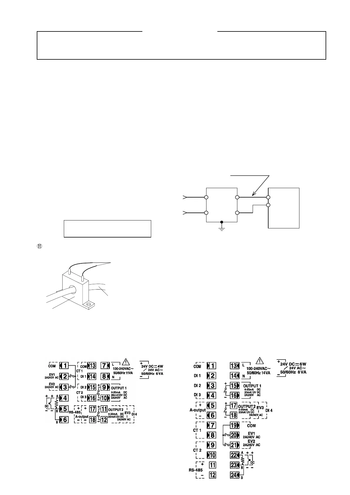
3-5. Terminal layout
Wire in accordance with the following terminal layout and terminal arrangement table.
SRS11 SRS13/SRS14
Recommended noise filter:
DENSEI-LAMBDA MAW-1202-22
Heater (load) wire
CT
To CT input terminal of
controller (no polarity)
Noise filter
Make this wire short.
Controller
100~
240V AC
50/60Hz
IN OUT
100~
240V AC
Ground
 Loading...
