Mark VII Restored Manual - V1.02 – Donated without cost to the world-wide Shopsmith Community - Everett L. Davis 2016 14
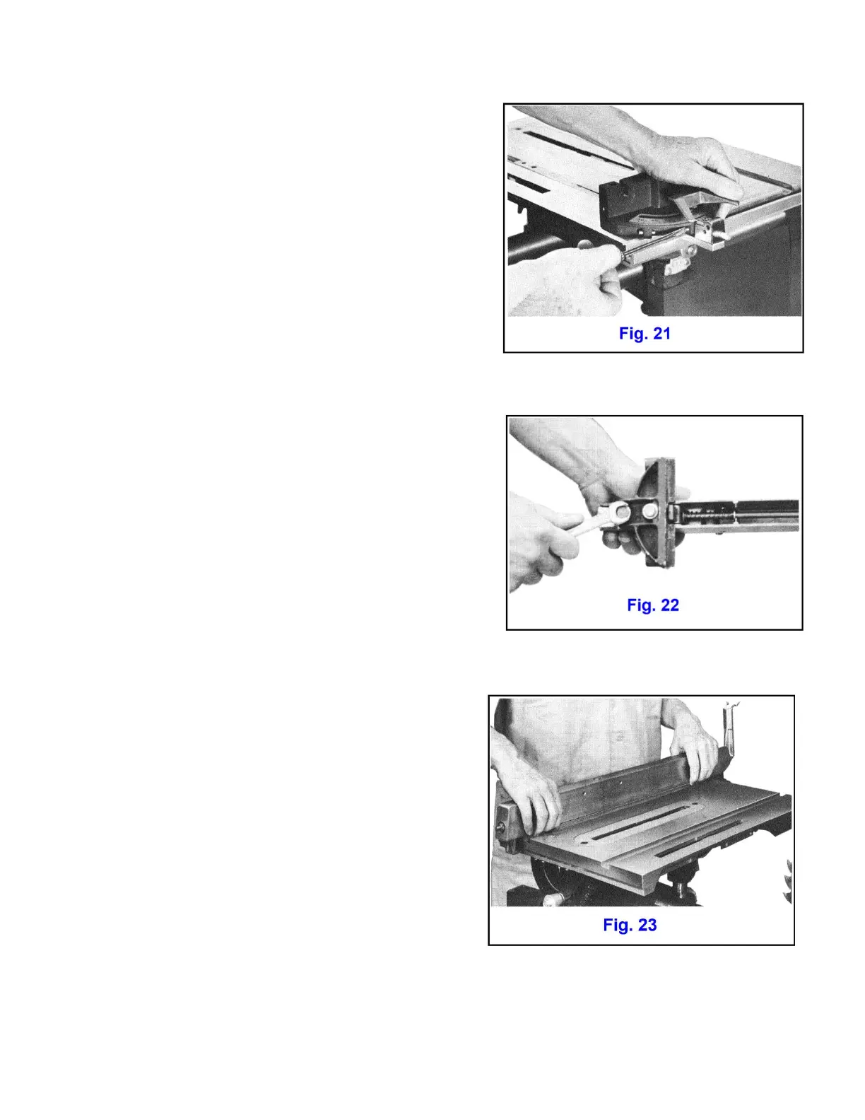
IF MITER GAUGE, AT 90 DEGREE SETTING, IS NOT
EXACTLY SQUARE TO BLADE
Raise lock lever and pull out miter gauge plunger (No. 3, Fig.
25). Adjust miter gauge head exactly square to blade and
lock in place.' Push in plunger and adjust auto-stop set screw
until it just bears against plunger (Fig. 21). Adjust miter gauge
vernier plate until middle "calibration is lined up exactly with
90 degree mark on miter gauge.
Unlock and turn miter gauge head until center vernier plate
mark is lined up with 45 degree mark on miter gauge. Push
in plunger and adjust 45 degree auto-stop set screw until it
bears against plunger. Make a similar adjustment on the opposite 45 degree auto-stop.
4 THE RIP FENCE, WHEN LOCKED, MUST BE PARALLEL
TO THE TABLE SLOTS
Check by locking rip fence on table, positioned so that one
side of fence is flush with one side of either table slot.
IF RIP FENCE IS NOT EXACTLY PARALLEL TO TABLE
SLOTS
Loosen the two cap screws which secure fence to base
casting (Fig. 22). By feeling with finger tips at both ends of
fence, set fence exactly parallel to either table slot (Fig. 23)
and lock by depressing locking handle. Retighten the two cap
screws while fence is locked in position.
5 THE EXTENSION TABLE MUST BE ALIGNED WITH
SAW TABLE
Check by setting extension table to height of saw table and
moving carriage to extreme right end. Place a straight
edge across front edges of table bars (Fig. 24).
IF IT IS NOT IN LINE ACROSS THE FRONT:
Loosen the four cap screws which secure saw table to
trunnions (No. 20. Fig. 26). Tap saw table forward or back
until front edge of table bar is in line with edge of
extension table bar. Retighten four cap screws turning
each a small amount until all four are secure. Recheck saw
table for alignment with saw blade as covered by step 2.