Shure Incorporated
8/45
◦
◦
◦
◦
◦
◦
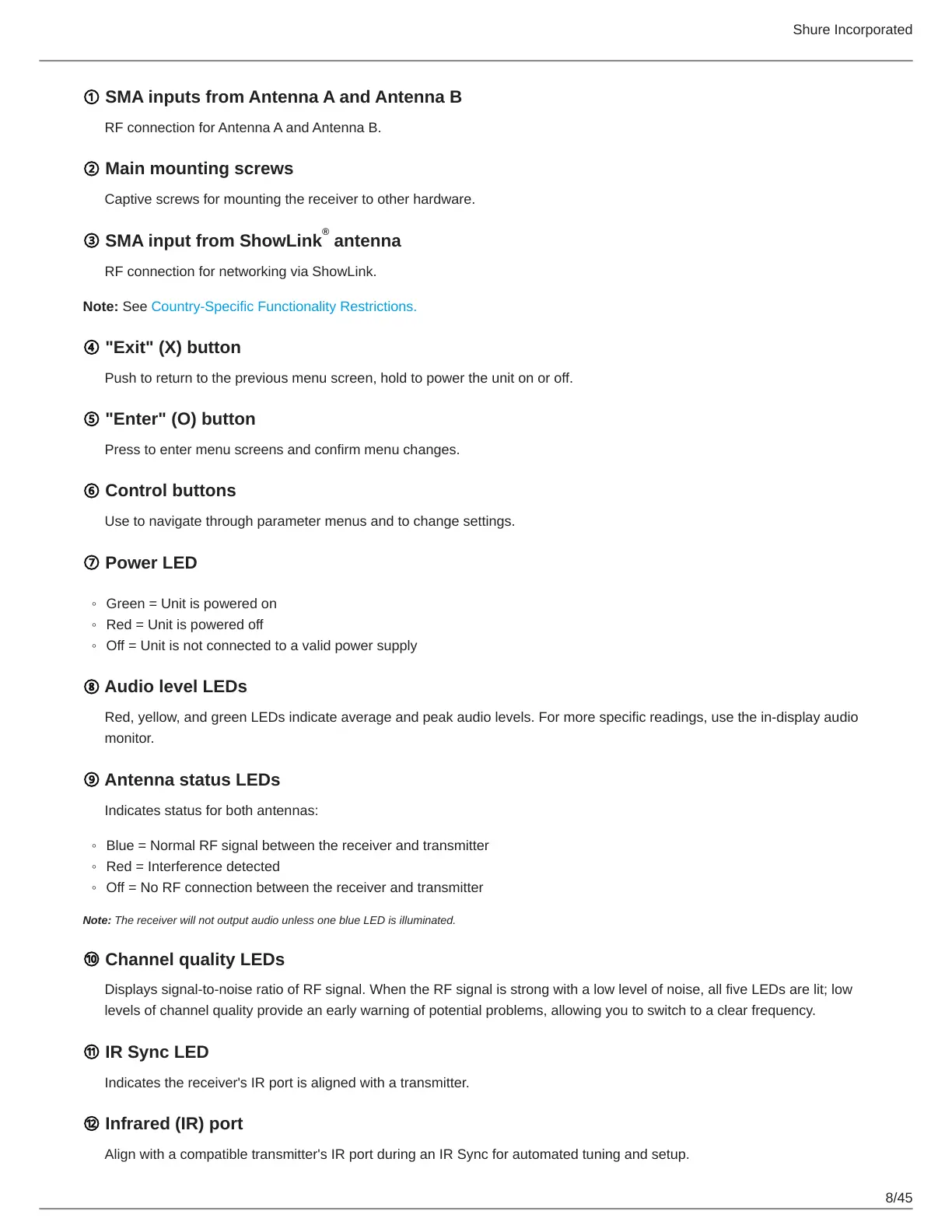
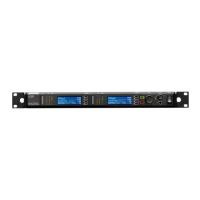
① SMA inputs from Antenna A and Antenna B
RF connection for Antenna A and Antenna B.
② Main mounting screws
Captive screws for mounting the receiver to other hardware.
③ SMA input from ShowLink antenna
RF connection for networking via ShowLink.
Note: See Country-Specific Functionality Restrictions.
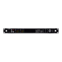
④ "Exit" (X) button
Push to return to the previous menu screen, hold to power the unit on or off.
⑤ "Enter" (O) button
Press to enter menu screens and confirm menu changes.
⑥ Control buttons
Use to navigate through parameter menus and to change settings.
⑦ Power LED
Green = Unit is powered on
Red = Unit is powered off
Off = Unit is not connected to a valid power supply
⑧ Audio level LEDs
Red, yellow, and green LEDs indicate average and peak audio levels. For more specific readings, use the in-display audio
monitor.
⑨ Antenna status LEDs
Indicates status for both antennas:
Blue = Normal RF signal between the receiver and transmitter
Red = Interference detected
Off = No RF connection between the receiver and transmitter
Note: The receiver will not output audio unless one blue LED is illuminated.
⑩ Channel quality LEDs
Displays signal-to-noise ratio of RF signal. When the RF signal is strong with a low level of noise, all five LEDs are lit; low
levels of channel quality provide an early warning of potential problems, allowing you to switch to a clear frequency.
⑪ IR Sync LED
Indicates the receiver's IR port is aligned with a transmitter.
⑫ Infrared (IR) port
Align with a compatible transmitter's IR port during an IR Sync for automated tuning and setup.
®