- 11 -
Before removing or installing any of these devices including CPU, DIMMs, Add-On
Cards, Cables, please make sure to unplug the onboard power connector.
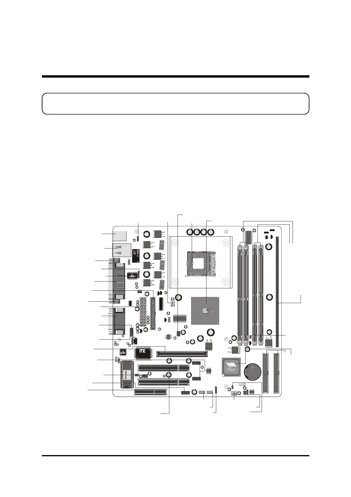
This section outlines how to install and configure your mainboard. Refer to the following
mainboard layout to help you to identify various jumpers, connectors, slots, and ports.
Then follow these steps designed to guide you through a quick and correct installation of
your system.
3.1 Step-by-Step Installation
3 HARDWARE INSTALLATION
Accessories Of MV43/MV43N
22144Q1 2124
RTM360-107R
9
3
7
1
8
C
F
R
T
M
6
8
0
-
2
5
5
R
KB_MS
USB
COM1
COM2 PRT
AUDIO_GAME1
C
D
1
CD2
D
D
R
2
D
D
R
1
IDE1
IDE2
FDCCN5
R
G
8
2
8
4
5
Q
C
2
2
E
S
PCI1
A
G
P
C
N
R
1
PCI1
PCI2
J
P
2
SIR1
J12
J
P
1
A
1
J
P
1
B
1
J
3
D
J2 /J3
J
3
C
J
3
B
J
3
A
J
2
D
J
2
C
J
2
B
J
2
A
J
1
6
JBAT1
1
1
1
1
SPK1
P
A
N
E
L
1
USB2
1
1
U
S
B
1
1
2
W
O
L
1
W
O
M
1
J
P
1
IT8705F
0232-FXS
Mf5920
CR2032
JAPAN STD
LITHIUM BATTERY
K T S
A
T
X
P
W
R
C
N
7
1
PANEL2
1
2
SYSTEM_FAN
C
P
U
_
F
A
N
One AGP 4x Slot
One CNR Slot
Extended four USB Connectors
header-USB1/ USB2
Keyboard Power On- JP2
Wake on LAN-WOL1
Speaker Connector-SPK1
System FAN
Wake on Modem-WOM1
USB & LAN(MV43N only)
Connectors
Parallel Connector
VIA6103 Phy(MV43N only)
LAN LED Indicator- J16
Serial Port
Connector (COM1)
VGA Connector
Panel1 Connector
Panel2 Connector
Serial infrared port-SIR1
Line-Out/Line-In/Mic-In/
Game/MIDI Connectors
Onboard Audio
Connectors- CD1/CD2
PS/2 Keyboard and
PS/2 Mouse Connectors
CPU FAN
ATX Power Connector
Clear CMOS - JBAT1
Sleep Switch-J12
T
w
o
E
-
I
D
E
C
o
n
n
e
c
t
o
r
s
V
I
A
8
2
3
5
C
h
i
p
s
e
t
Floppy Connector
T
w
o
1
6
8
p
i
n
S
D
R
D
I
M
M
S
l
o
t
s
D
R
A
M
V
o
l
t
a
g
e
-
J
P
1
T
w
o
1
8
4
p
i
n
D
D
R
D
I
M
M
S
l
o
t
s
D
D
R
/
S
D
R
D
R
A
M
T
y
p
e
S
e
l
e
c
t
o
r
-
J
2
A
/
B
/
C
/
D
J
3
A
/
B
/
C
/
D
/
Socket 478
VIA 8751 Chipset