Contents
Warning! 2
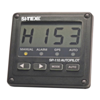
SP-110C Autopilot System 3
Initial Operational Settings (SP-110C) –
Without Rudder Feedback 17
Turn Ratio 18
Initial Operational Settings (SP-110CR) –
With Rudder Feedback 9
Compass Alignment 10
Rudder End Limits – Automatic Set Up
(Rudder Feedback Required) 11
Rudder End Limits – Manual Set Up
Main Screen Explained 22
Manual Steer Mode 22
Auto Steer Mode 23
GPS Steer Mode 24
Error Messages 25
(Rudder Feedback Required) 12
Rudder Ratio (Proportional Gain) 13
Rudder Sensitivity (Rudder Tolerance) 13
Error Gain (Integral Control Gain) 13
Rate of Change
(Derivative Gain Multiplier) 14
Rate of Turn (Max Turn Angle) 14
Dead Band 15
BOD Correction (GPS Mode) 15
Reverse Delay 15
Advanced Option s
(Recommended for Installers Only) 25
Steering Menu 26
Coms Menu 27
Elecom Menu (Compass Calibration) 27
GPS Menu (NMEA Corrections) 29
Factory Default 29
About 30
Setting up Your GPS Unit 30
Minimum Speed 16
Backlight Bright 16
Wind Mode
SP-110C Alarms 31
Definition of Terms 31
(Requires MWV NMEA Data Input) 16
Testing Procedure 32
Trouble Shooting 33
Declaration of Conformity 34
Warranty 35
Additional Information 35