Access for wiring must be provided.
Cables have to be run to the power
switchboard, display, compass,
rudder feedback (if fitted) and
drive unit.
All wiring should be kept as far as
possible from radio aerials and aerial
cables to prevent interference to
the radio and to prevent transmitted
signals from the radio influencing
the SP-110C.
The compass must be mounted a
minimum distance of 1 metre from
any boat compass, radios, speakers
or other products with magnetic
properties to avoid interference. The
SP-110C must have a direct
connection to power supply via a 15
amp circuit breaker or a 15 amp
fused circuit and an isolating switch.
Display Unit
Position:
The SP-110C Head unit should be
mounted in a position accessible to
the steering position and protected
from direct rain or salt water.
• Select a dry position
• For in dash mounting cut a 70mm
(2.5”) hole (an optional mounting
bracket is available and may be
used for display mounting – see
your supplier)
• Drill mounting screw holes
• Mount the display using screws
supplied (304 SS – 6G)
• Fit dome plugs to cover screws
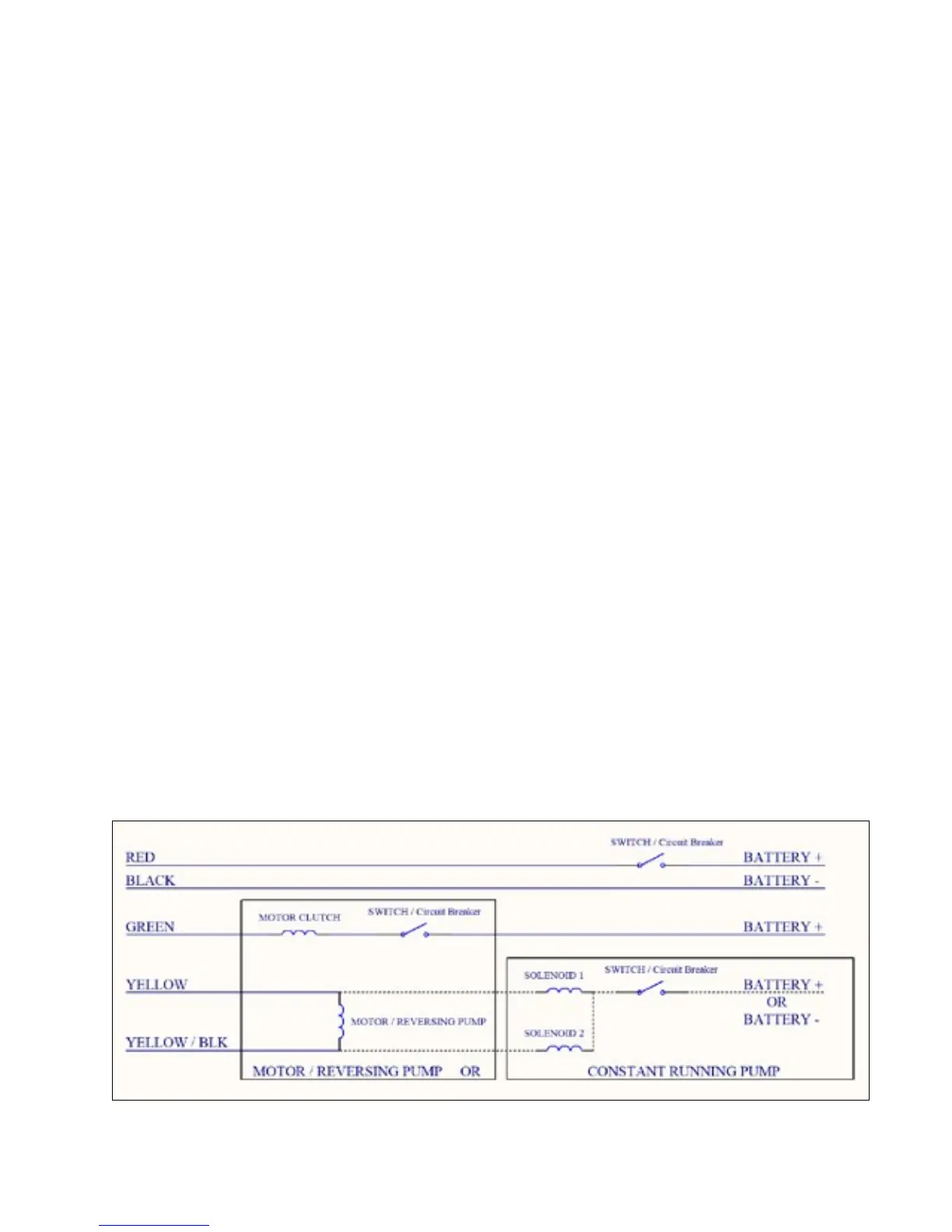
• Ensure motor (yellow) and clutch
(green) wires are not exposed
before connecting power to the
SP-110C
• Connect red wire to + 12 volts DC
(Positive)
• Connect black wire to - 12 volts DC
(Negative)
Figure 1: (below) Wiring Diagram
4 of 35
SI-TEX SP-110C