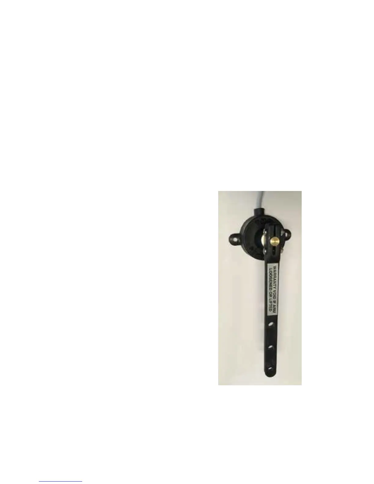
Rudder Feedback Unit
*Only for SP-110CR version.
The SP-110CR Autopilot is
supplied with an RFU (rudder
feedback unit), which provides to
the pilot a precise position of the
boat rudder.
Position:
• Refer to diagram on page 7
• Mount rudder feedback adjacent to
the tiller (rudder feedback movement
must copy the angular movement
of the tiller). Use mounting bracket
if required
• Note markings on the rudder
feedback unit. P & S indicate the
required movement of the tiller
for course correction (Port and
Starboard).
• Rudder feedback is mounted
with shaft uppermost
• Fit snap lock swivel joint to rudder
feedback arm
• Fit link block to tiller arm
• Fit link arm from rudder feedback
to tiller – adjust for correct angle
• Route cable to SP-110CR
display position
• Connect rudder feedback cable
to SP-110CR rudder socket
• When installation is complete,
slowly move the steering by hand
to ensure:
a)
The direction indicated on the
top of the RFU is correct
b)
No undue mechanical strain
is placed on the feedback or
linkage
Figure 4: Rudder feedback unit.



 To Next Page