SP-110C Autopilot
System
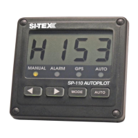
The SP-110C Autopilot control
system comprises the following units:
• SP-110C display and control head.
• SI-TEX E-compass
• Rudder Feedback Unit
(SP-110CR only).
In addition the SP-110C has to be
connected to a drive unit which
controls the rudder actuator system
in order to complete the full autopilot
system. The actuator system
provides the physical movement to
the rudder responding to the direction
of control signals provided by the SP-
110C. A rudder actuator system
comprises one of the following:
• Hydraulic system with helm pump
and ram
• Mechanical steering system
The autopilot should be connected
to a:
• Reversing motor / pump set
connected into the existing
hydraulic steering system; or
• Continuously running Hydraulic
Pump with solenoid control.
• Reversing mechanical drive unit
connected to the existing steering
mechanism
Block Diagram of full system
*Dashed line (RFU) only for
applicable for SP-110CR.
The SP-110C display provides full
control of the autopilot system and
indicates different modes for heading,
course to steer and rudder angle.
The system requires a supply voltage
of 12-24 Volts DC (Up to 29V During
Charging)
Installation of System
Components
Ensure you have all the components
of the autopilot.
Tools required:
• Screwdrivers – flat blade and
Phillips head
• Side cutting pliers
• Wire strippers
• Spanners (various) or
adjustable spanner
• 70mm hole saw
• Power drill + assortment of drill bits
• Multi meter (DVM)
• Ancillaries such as tape,
connecting block, screws, cable
ties, etc.
SI-TEX SP-110C 3 of 35